Sony XDSPD2000 User Manual (XDS-PD1000 and XDS-PD2000 Operation Manual for Fir - Page 123
M3: OTHERS: Other setting items, PB-STOP STATUS [P.STP]
 |
View all Sony XDSPD2000 manuals
Add to My Manuals
Save this manual to your list of manuals |
Page 123 highlights
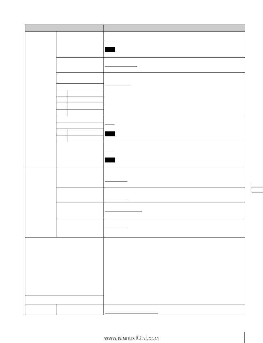
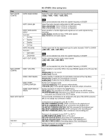
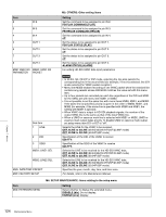
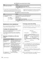
Item M37: AUDIO CONFIG M370: HEAD ROOM M371: DATA LEN M372: NON-AUDIO INPUT Sub-item 1 Tr1/Tr2 2 Tr3/Tr4 3 Tr5/Tr6 4 Tr7/Tr8 M373: IN LEVEL Sub-item 1 CH1/3/5/7 2 CH2/4/6/8 M377: OUT LEVEL M39: OTHER CONFIG M391: VITC REC M395: FRMT MEDIA M397: PORT CONFIGURATION M398: VDCP STATUS MODE M3A: GPIO SETUP Sub-item 1 IN 1 M3: OTHERS: Other setting items Setting Select the audio reference level (headroom). -20dB, -18dB, -16dB, -12dB, EBUL Note EBUL can be selected only when the system frequency is 50i/25P. Select the audio channel configuration for IMX recording. 16bit x 8ch [16x8]: 16-bit, 8-channel configuration 24bit x 4ch [24x4]: 24-bit, 4-channel configuration Select whether to handle digital audio signals as non-audio signals during recording. audio [Audio]: Handle as linear PCM audio signals. data: Handle as non-audio signals. Set the upper limit for the signal level input to audio channels 1/3/5/7 or 2/4/6/8. +4dB, 0dB, -3dB, -6dB, EBUL Note EBUL can be selected only when the system frequency is 50i/25P. Set the reference level for audio output signals. +4dB, 0dB, -3dB, -6dB, EBUL Note EBUL can be selected only when the system frequency is 50i/25P. Select whether to record the VITC in the input HDSDI signals in the LTC user bits area. disable [dis]: Do not record. enable [ena]: Record. Specify whether to disable the Format Media command of the Clip Menu. disable [dis]: Disable the Format Media command. enable [ena]: Enable the Format Media command. Set the port operation mode. 1-in/1-out mode [i/o]: Ports operate independently. VTR mode [vtr]: Ports operate together as input and output connectors. Set the operations to reflect in the VDCP status. VDCP [vdc]: Only operations via VDCP are reflected in the VDCP status. VDCP/FP/NetRMT [all]: Operations from VDCP, remote connection, and the front panel are reflected in the VDCP status. Set commands and statuses to be assigned to the pins of the GPIO connector. off: Do not assign any command or status. Commands to be assigned to pins IN 1 to IN 4: PB-STOP COMMAND [P.STP]: STOP command to the playback port PB-PLAY COMMAND [PLAY]: PLAY command to the playback port PB-RECUE COMMAND [RECUE]: RECUE command to the playback port REC-STOP COMMAND [R.STP]: STOP command to the recording port REC-REC COMMAND [REC]: REC command to the recording port Statuses to be assigned to pins OUT 1 to OUT 4: ALARM STATUS [ALARM]: Status of the alarm PB-STOP STATUS [P.STP]: Stop status of the playback port. PB-PLAY STATUS [PLAY]: Playback status of the playback port REC-REC STATUS [REC]: Recording status of the recording port Set the command to be assigned to pin IN 1. PB-STOP COMMAND [P.STP] Chapter 7 Menus 123 Maintenance Menu
-
 1
1 -
2
-
3
-
4
-
5
-
6
-
7
-
8
-
9
-
10
-
11
-
12
-
13
-
14
-
15
-
16
-
17
-
18
-
19
-
20
-
21
-
22
-
23
-
24
-
25
-
26
-
27
-
28
-
29
-
30
-
31
-
32
-
33
-
34
-
35
-
36
-
37
-
38
-
39
-
40
-
41
-
42
-
43
-
44
-
45
-
46
-
47
-
48
-
49
-
50
-
51
-
52
-
53
-
54
-
55
-
56
-
57
-
58
-
59
-
60
-
61
-
62
-
63
-
64
-
65
-
66
-
67
-
68
-
69
-
70
-
71
-
72
-
73
-
74
-
75
-
76
-
77
-
78
-
79
-
80
-
81
-
82
-
83
-
84
-
85
-
86
-
87
-
88
-
89
-
90
-
91
-
92
-
93
-
94
-
95
-
96
-
97
-
98
-
99
-
100
-
101
-
102
-
103
-
104
-
105
-
106
-
107
-
108
-
109
-
110
-
111
-
112
-
113
-
114
-
115
-
116
-
117
-
 118
118 -
 119
119 -
 120
120 -
 121
121 -
 122
122 -
 123
123 -
 124
124 -
 125
125 -
 126
126 -
 127
127 -
 128
128 -
129
-
130
-
131
-
132
-
133
-
134
-
135
-
136
-
137
-
138
-
139
-
140
-
141
-
142
-
143
-
144
-
145
-
146
-
147
-
148
-
149
-
150
-
151
-
152
-
153
-
154
-
155
-
156
-
157
-
158
-
159
-
160
-
161
 |
 |