Sony XDSPD2000 User Manual (XDS-PD1000 and XDS-PD2000 Operation Manual for Fir - Page 28
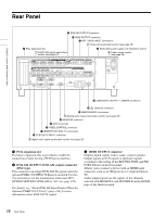
HD/SD-SDI INPUT HD-SDI/SD-SDI signal input, HD-SDI OUTPUT1 HD-SDI signal output 1
 |
View all Sony XDSPD2000 manuals
Add to My Manuals
Save this manual to your list of manuals |
Page 28 highlights
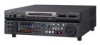
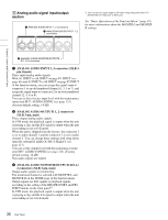
Chapter 2 Names and Functions of Parts a HD/SD-SDI INPUT (HD-SDI/SD-SDI signal input) connector (BNC type) This inputs an HD-SDI or SD-SDI format video/audio signal. When the optional PDBK-202 MPEG TS Board is installed, you can input DVB-ASI TS signals to this connector. When inputting DVB-ASI TS signals, it is necessary to set the maintenance menu item M22: OPTION SETTING >DVB-ASI to "on" (see page 122), and set V INPUT to "DVB-ASI" on page P1 INPUT of the function menu (see page 46). For details, see "About DVB-ASI Input/Output (When the Optional PDBK-202 Is Used)" (page 144) for more information about DVB-ASI TS signals. b HD-SDI OUTPUT1 (HD-SDI signal output) 1, 2 (SUPER) connectors (BNC type) These output HD-SDI format video/audio playback signals. In VTR mode, the playback signal is output when the unit is playing a clip, and the E-E signal is output when the unit is recording or set to E-E mode. You can superimpose timecodes or error messages on the output of the 2 (SUPER) connector with the setting for CHAR SEL on the HOME page of the function menu and with the setting for setup menu item 028 HD CHARACTER. You can always disable to superimpose the data independent of the setting for CHAR SEL with the setting for setup menu item 028. See "Basic Operations of the Function Menu" (page 45) for more information about the CHAR SEL settings. See page 102 for more information about the setup menu item 028 HD CHARACTER. To treat the input and output signals of these connectors as non-audio signals, set the maintenance menu item M37: AUDIO CONFIG >M372: NON-AUDIO INPUT (recording) (see page 123). c SD-SDI OUTPUT1 (SD-SDI signal output) 1, 2 (SUPER) connectors (BNC type) These output SD-SDI format video/audio playback signals. In VTR mode, the playback signal is output when the unit is playing a clip, and the E-E signal is output when the unit is recording or set to E-E mode. When the unit is shipped from the factory, audio signal output is eight channels with no switching, and RP188 timecode output is set to on. You can change these settings with setup menu item 828 SDI AUDIO OUTPUT SELECT and setup menu item 920 SD-SDI H-ANC CONTROL (see page 116). You can superimpose timecodes or error messages on the output of the 2 (SUPER) connector with the setting for CHAR SEL on the HOME page of the function menu and with the setting for setup menu item 027 SD CHARACTER. You can always disable to superimpose the data independent of the setting for CHAR SEL with the setting for setup menu item 027. See "Basic Operations of the Function Menu" (page 45) for more information about the CHAR SEL settings. See page 102 for more information about the setup menu item 027 SD CHARACTER. d HD-SDI MONITOR/OUTPUT2 (HD-SDI signal monitor output) 1, 2 (SUPER) connectors (BNC type) Allows you to connect an HD monitor with an HD-SDI input connector. This outputs HD-SDI format video/audio signals. Output signals are E-E signals or playback signals, according to the setting of the REC/PB2 PORT and PB1 PORT buttons on the front panel.1) In VTR mode, the playback signal is output when the unit is playing a clip, and the E-E signal is output when the unit is recording or set to E-E mode. You can superimpose timecodes or error messages on the output of the 2 (SUPER) connector with the setting for CHAR SEL on the HOME page of the function menu and with the setting for setup menu item 028 HD CHARACTER. You can always disable to superimpose the data independent of the setting for CHAR SEL with the setting for setup menu item 028. 1) You can set E-E signal output at all times using setup menu item 156 MONITOR OUT SELECT to REC port. See "Basic Operations of the Function Menu" (page 45) for more information about the CHAR SEL settings. See page 102 for more information about the setup menu item 028 HD CHARACTER. e SD-SDI MONITOR/OUTPUT2 (SD-SDI signal monitor output) 1, 2 (SUPER) connectors (BNC type) Allows you to connect an SD monitor with an SD-SDI input connector. This outputs SD-SDI format video/audio signals. Output signals are E-E signals or playback signals, according to the setting of the REC/PB2 PORT and PB1 PORT buttons on the front panel.1) In VTR mode, the playback signal is output when the unit is playing a clip, and the E-E signal is output when the unit is recording or set to E-E mode. You can superimpose timecodes or error messages on the output of the 2 (SUPER) connector with the setting for CHAR SEL on the HOME page of the function menu and with the setting for setup menu item 027 SD CHARACTER. You can always disable to superimpose 28 Rear Panel
-
 1
1 -
2
-
3
-
4
-
5
-
6
-
7
-
8
-
9
-
10
-
11
-
12
-
13
-
14
-
15
-
16
-
17
-
18
-
19
-
20
-
21
-
22
-
 23
23 -
 24
24 -
 25
25 -
 26
26 -
 27
27 -
 28
28 -
 29
29 -
 30
30 -
 31
31 -
 32
32 -
 33
33 -
34
-
35
-
36
-
37
-
38
-
39
-
40
-
41
-
42
-
43
-
44
-
45
-
46
-
47
-
48
-
49
-
50
-
51
-
52
-
53
-
54
-
55
-
56
-
57
-
58
-
59
-
60
-
61
-
62
-
63
-
64
-
65
-
66
-
67
-
68
-
69
-
70
-
71
-
72
-
73
-
74
-
75
-
76
-
77
-
78
-
79
-
80
-
81
-
82
-
83
-
84
-
85
-
86
-
87
-
88
-
89
-
90
-
91
-
92
-
93
-
94
-
95
-
96
-
97
-
98
-
99
-
100
-
101
-
102
-
103
-
104
-
105
-
106
-
107
-
108
-
109
-
110
-
111
-
112
-
113
-
114
-
115
-
116
-
117
-
118
-
119
-
120
-
121
-
122
-
123
-
124
-
125
-
126
-
127
-
128
-
129
-
130
-
131
-
132
-
133
-
134
-
135
-
136
-
137
-
138
-
139
-
140
-
141
-
142
-
143
-
144
-
145
-
146
-
147
-
148
-
149
-
150
-
151
-
152
-
153
-
154
-
155
-
156
-
157
-
158
-
159
-
160
-
161
 |
 |