Sony XDSPD2000 User Manual (XDS-PD1000 and XDS-PD2000 Operation Manual for Fir - Page 30
Analog audio signal input/output, ANALOG AUDIO MONITOR/OUTPUT2 R/1, L
 |
View all Sony XDSPD2000 manuals
Add to My Manuals
Save this manual to your list of manuals |
Page 30 highlights
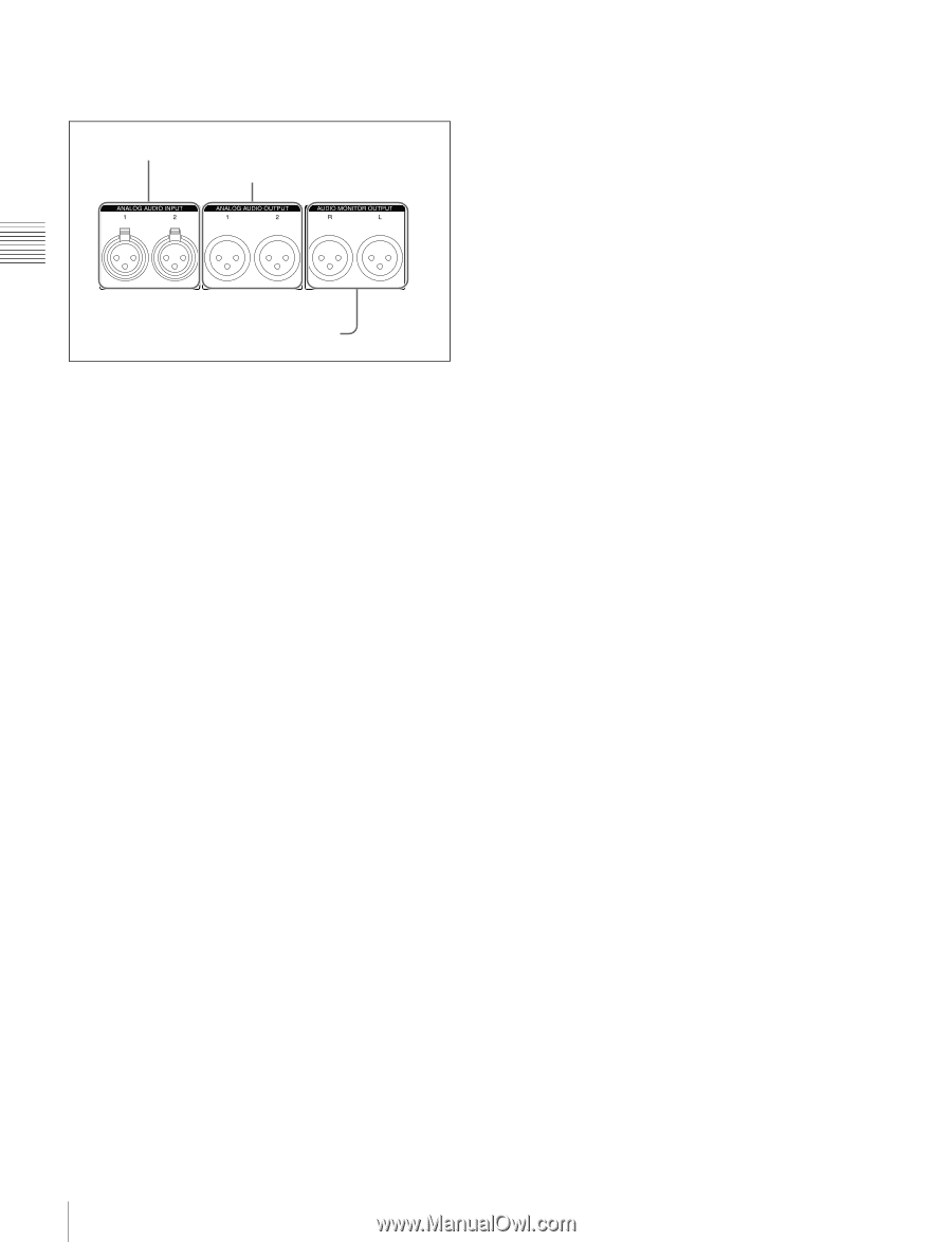
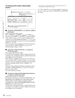
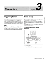
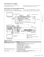
5 Analog audio signal input/output section 1 ANALOG AUDIO INPUT 1, 2 connectors 2 ANALOG AUDIO OUTPUT1 1, 2 connectors 1) You can set E-E signal output at all times using setup menu item 156 MONITOR OUT SELECT to REC port. See "Basic Operations of the Function Menu" (page 45) for more information about the MONITR L and MONITR R settings. Chapter 2 Names and Functions of Parts 3 ANALOG AUDIO MONITOR/OUTPUT2 R/1, L/2 connectors a ANALOG AUDIO INPUT 1, 2 connectors (XLR 3pin, female) These input analog audio signals. With A1 INPUT to A4 INPUT on page P1 INPUT (see page 46) and A5 INPUT to A8 INPUT on page P2 INPUT of the function menu, you can assign the signal input to connector 1 to an odd numbered channel (1, 3, 5 or 7), and assign the signal input to connector 2 to an even numbered channel (2, 4, 6 or 8). You can set the reference input level with the maintenance menu item M37: AUDIO CONFIG (see page 123). (Factory default setting: +4 dB) b ANALOG AUDIO OUTPUT1 1, 2 connectors (XLR 3-pin, male) These output analog audio signals. In VTR mode, the playback signal is output when the unit is playing a clip, and the E-E signal is output when the unit is recording or set to E-E mode. When the unit is shipped from the factory, the connector 1 is set to audio channel 1, and the connector 2 is set to audio channel 2. You can change these settings with setup menu item 824 ANALOG LINE OUTPUT SELECT (see page 115). You can set the output level with the maintenance menu item M37: AUDIO CONFIG (see page 123). (Factory default setting: +4 dB) Non-audio signals are muted. c ANALOG AUDIO MONITOR/OUTPUT2 R/1, L/ 2 connectors (XLR 3-pin, male) Output audio signals for monitoring. The monitored channel is selected with MONITR L and MONITR R on the HOME page of the function menu. Output signals are E-E signals or playback signals, according to the setting of the REC/PB2 PORT and PB1 PORT buttons on the front panel.1) In VTR mode, the playback signal is output when the unit is playing a clip, and the E-E signal is output when the unit is recording or set to E-E mode. 30 Rear Panel
-
 1
1 -
2
-
3
-
4
-
5
-
6
-
7
-
8
-
9
-
10
-
11
-
12
-
13
-
14
-
15
-
16
-
17
-
18
-
19
-
20
-
21
-
22
-
23
-
24
-
 25
25 -
 26
26 -
 27
27 -
 28
28 -
 29
29 -
 30
30 -
 31
31 -
 32
32 -
 33
33 -
 34
34 -
 35
35 -
36
-
37
-
38
-
39
-
40
-
41
-
42
-
43
-
44
-
45
-
46
-
47
-
48
-
49
-
50
-
51
-
52
-
53
-
54
-
55
-
56
-
57
-
58
-
59
-
60
-
61
-
62
-
63
-
64
-
65
-
66
-
67
-
68
-
69
-
70
-
71
-
72
-
73
-
74
-
75
-
76
-
77
-
78
-
79
-
80
-
81
-
82
-
83
-
84
-
85
-
86
-
87
-
88
-
89
-
90
-
91
-
92
-
93
-
94
-
95
-
96
-
97
-
98
-
99
-
100
-
101
-
102
-
103
-
104
-
105
-
106
-
107
-
108
-
109
-
110
-
111
-
112
-
113
-
114
-
115
-
116
-
117
-
118
-
119
-
120
-
121
-
122
-
123
-
124
-
125
-
126
-
127
-
128
-
129
-
130
-
131
-
132
-
133
-
134
-
135
-
136
-
137
-
138
-
139
-
140
-
141
-
142
-
143
-
144
-
145
-
146
-
147
-
148
-
149
-
150
-
151
-
152
-
153
-
154
-
155
-
156
-
157
-
158
-
159
-
160
-
161
 |
 |