Sony XDSPD2000 User Manual (XDS-PD1000 and XDS-PD2000 Operation Manual for Fir - Page 23
Clip information, Operation status display
 |
View all Sony XDSPD2000 manuals
Add to My Manuals
Save this manual to your list of manuals |
Page 23 highlights
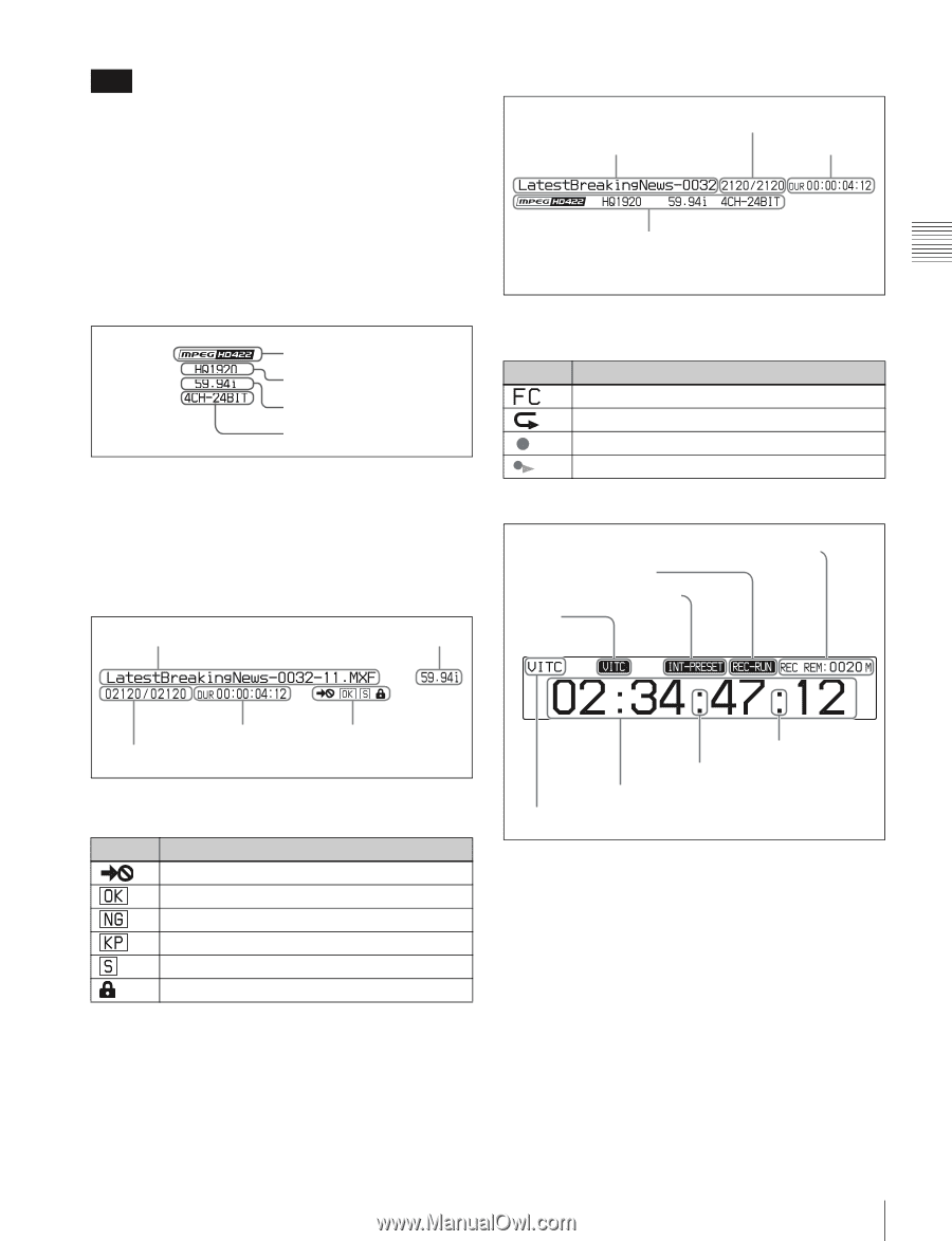
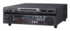
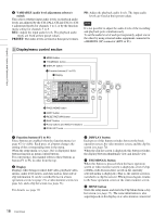
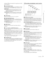
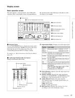
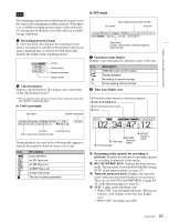
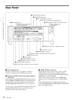
Chapter 2 Names and Functions of Parts Note The remaining capacity of recordable resource space is not the same as the remaining recording capacity. When there is no available recording resource space is left on the disc, file writing may be disabled even with sufficient available storage remaining. e Recording/playback format In 1-in/1-out mode, this displays the recording format when a record port is selected or the playback clip format when a playback port is selected. In VTR mode, this displays the format of the clip being played. Codec Video format System frequency Audio format f Clip information Displays clip information. The display varies depending on the clip playback mode.1) 1) The clip playback mode setting is switched using maintenance menu item M397 PORT CONFIGURATION. In 1-in/1-out mode Clip name System frequency In VTR mode Clip number/total number of clips Clip name Duration Clip format (Codec, video format, System frequency, Audio format) g Operation status display Displays icons indicating the operation status of this unit. Icon Description 1080/720 cross-convert output Repeat playback Recording to internal storage Chase playing internal storage h Time data display area A Remaining media capacity for recording or playback B REC RUN/FREE RUN C Timecode generator mode D VITC Duration Property icons Clip number/total number of clips During playback, the icons in the following table appear to indicate the properties that have been set in a clip. Icon Description Copy restricted An OK flag is set An NG flag is set A KEEP flag is set A shot mark is set The clip is locked (protected) G DF/NDF F Time data indication (TCR) E Time data type G DF/NDF indication (TCG) A Remaining media capacity for recording or playback: Displays the amount of remaining capacity for recording or playback on the media. B REC RUN/FREE RUN: Displays the timecode run mode. The run mode is set with RUN MODE on page P4 TC of the function menu (see page 47). C Timecode generator mode: Displays the timecode source and generation method (preset or regenerate). These are set with TCG and PRST/RGN on page P4 TC of the function menu (see page 47). D VITC: Lights in the following cases. • When VITC is read in playback mode. (This has no relations to the display in the time data display area.) • When VITC recording is possible. 23 Front Panel
-
 1
1 -
2
-
3
-
4
-
5
-
6
-
7
-
8
-
9
-
10
-
11
-
12
-
13
-
14
-
15
-
16
-
17
-
 18
18 -
 19
19 -
 20
20 -
 21
21 -
 22
22 -
 23
23 -
 24
24 -
 25
25 -
 26
26 -
 27
27 -
 28
28 -
29
-
30
-
31
-
32
-
33
-
34
-
35
-
36
-
37
-
38
-
39
-
40
-
41
-
42
-
43
-
44
-
45
-
46
-
47
-
48
-
49
-
50
-
51
-
52
-
53
-
54
-
55
-
56
-
57
-
58
-
59
-
60
-
61
-
62
-
63
-
64
-
65
-
66
-
67
-
68
-
69
-
70
-
71
-
72
-
73
-
74
-
75
-
76
-
77
-
78
-
79
-
80
-
81
-
82
-
83
-
84
-
85
-
86
-
87
-
88
-
89
-
90
-
91
-
92
-
93
-
94
-
95
-
96
-
97
-
98
-
99
-
100
-
101
-
102
-
103
-
104
-
105
-
106
-
107
-
108
-
109
-
110
-
111
-
112
-
113
-
114
-
115
-
116
-
117
-
118
-
119
-
120
-
121
-
122
-
123
-
124
-
125
-
126
-
127
-
128
-
129
-
130
-
131
-
132
-
133
-
134
-
135
-
136
-
137
-
138
-
139
-
140
-
141
-
142
-
143
-
144
-
145
-
146
-
147
-
148
-
149
-
150
-
151
-
152
-
153
-
154
-
155
-
156
-
157
-
158
-
159
-
160
-
161
 |
 |