Sony XDSPD2000 User Manual (XDS-PD1000 and XDS-PD2000 Operation Manual for Fir - Page 26
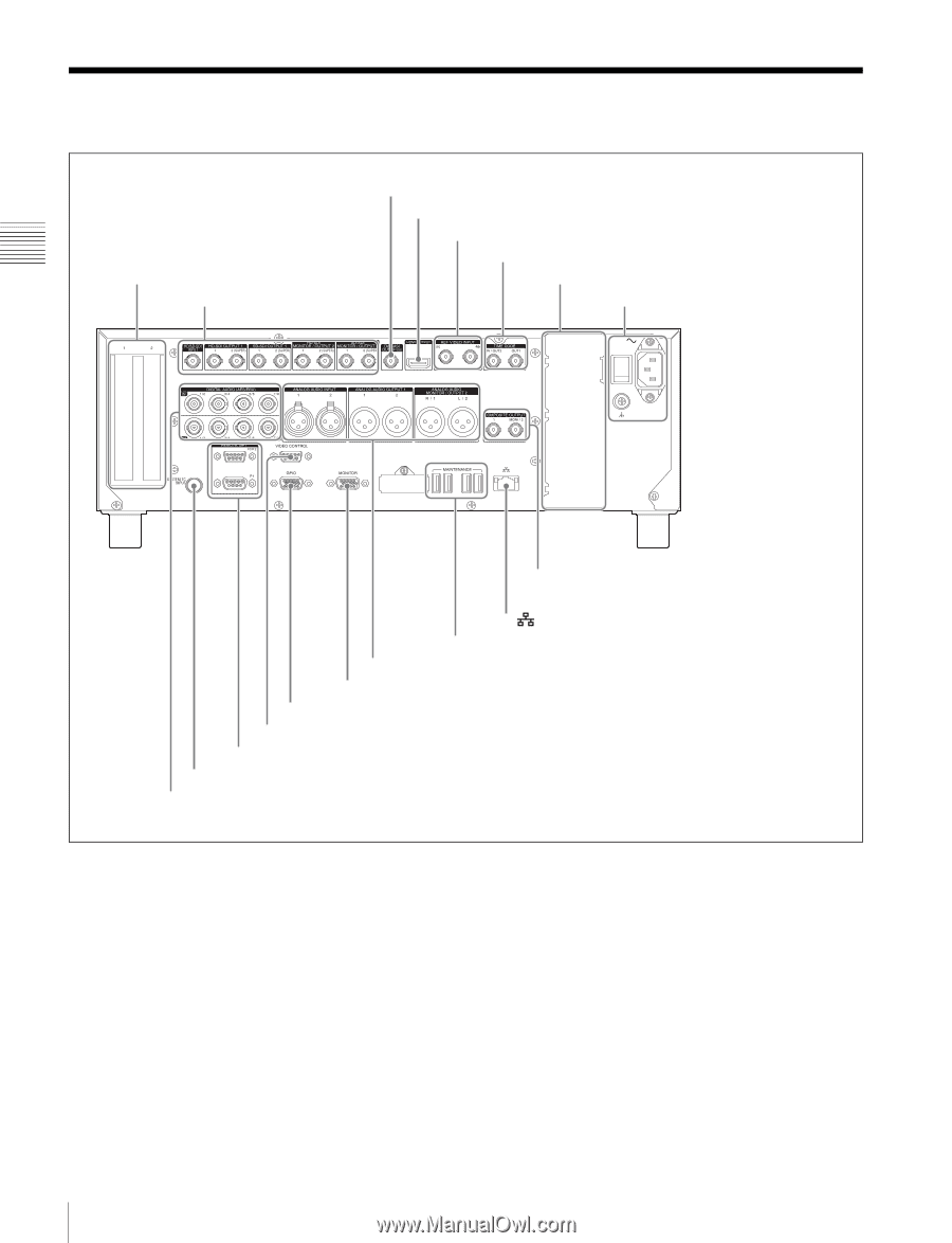
Rear Panel
 |
View all Sony XDSPD2000 manuals
Add to My Manuals
Save this manual to your list of manuals |
Page 26 highlights
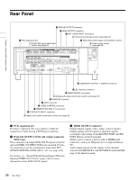
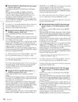
Rear Panel 2 DVB-ASI OUTPUT connector 3 HDMI OUTPUT connector 4 REF. VIDEO INPUT connectors 2 Timecode input/output section (see page 29) 1 PCIe expansion slot 1 HD/SD-SDI signal input/output section (see page 27) 5 Redundant power supply unit installation section 3 Power supply section (see page 29) Chapter 2 Names and Functions of Parts qd COMPOSITE OUTPUT 1, MONI/2 connectors qs (network) connector qa MAINTENANCE connectors 5 Analog audio signal input/output section (see page 30) q; MONITOR connector 9 GPIO connector 8 VIDEO CONTROL connector 7 REMOTE (9P) R/P2, P1 connectors 6 SYSTEM TC INPUT connector 4 Digital audio signal input/output section (see page 29) a PCIe expansion slot For future expansion, this is provided to enable the connection of units having a PCI Express interface. b DVB-ASI OUTPUT (DVB-ASI output) connector (BNC type) This connector can output DVB-ASI TS signals when the optional PDBK-202 MPEG TS Board is installed. For this, it is necessary to set the maintenance menu item M22: OPTION SETTING >DVB-ASI to "on" (see page 122). For details, see "About DVB-ASI Input/Output (When the Optional PDBK-202 Is Used)" (page 144) for more information about DVB-ASI TS signals. c HDMI OUTPUT connector Outputs digital signals (video, audio, control signals). Output signals are E-E signals or playback signals, according to the setting of the REC/PB2 PORT and PB1 PORT buttons on the front panel. Allows you to connect a device with an HDMI input connector, such as an HD projector or a high-definition TV. Audio output signals are the signals of the channels selected with MONITR L and MONITR R on the HOME page of the function menu. 26 Rear Panel
-
 1
1 -
2
-
3
-
4
-
5
-
6
-
7
-
8
-
9
-
10
-
11
-
12
-
13
-
14
-
15
-
16
-
17
-
18
-
19
-
20
-
 21
21 -
 22
22 -
 23
23 -
 24
24 -
 25
25 -
 26
26 -
 27
27 -
 28
28 -
 29
29 -
 30
30 -
 31
31 -
32
-
33
-
34
-
35
-
36
-
37
-
38
-
39
-
40
-
41
-
42
-
43
-
44
-
45
-
46
-
47
-
48
-
49
-
50
-
51
-
52
-
53
-
54
-
55
-
56
-
57
-
58
-
59
-
60
-
61
-
62
-
63
-
64
-
65
-
66
-
67
-
68
-
69
-
70
-
71
-
72
-
73
-
74
-
75
-
76
-
77
-
78
-
79
-
80
-
81
-
82
-
83
-
84
-
85
-
86
-
87
-
88
-
89
-
90
-
91
-
92
-
93
-
94
-
95
-
96
-
97
-
98
-
99
-
100
-
101
-
102
-
103
-
104
-
105
-
106
-
107
-
108
-
109
-
110
-
111
-
112
-
113
-
114
-
115
-
116
-
117
-
118
-
119
-
120
-
121
-
122
-
123
-
124
-
125
-
126
-
127
-
128
-
129
-
130
-
131
-
132
-
133
-
134
-
135
-
136
-
137
-
138
-
139
-
140
-
141
-
142
-
143
-
144
-
145
-
146
-
147
-
148
-
149
-
150
-
151
-
152
-
153
-
154
-
155
-
156
-
157
-
158
-
159
-
160
-
161
 |
 |