Sony XDSPD2000 User Manual (XDS-PD1000 and XDS-PD2000 Operation Manual for Fir - Page 16
Port and media selection INTERNAL internal storage ACCESS indicator
 |
View all Sony XDSPD2000 manuals
Add to My Manuals
Save this manual to your list of manuals |
Page 16 highlights
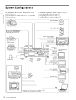
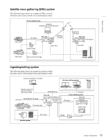
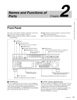
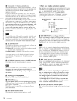
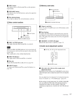
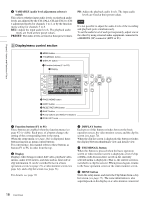
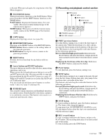
Chapter 2 Names and Functions of Parts c On/standby (1) button and indicator When the main power switch on the rear panel is in the on position, this switches the unit between the operating state (the indicator is lit green) and the standby state (the indicator is lit red). To put the unit into the operating state, press this button and hold it down for a short time (0.25 seconds or longer) while the indicator is lit red. The indicator changes to lit green, and the unit enters the operating state. To put the unit into the standby state, press this button and hold it down for a longer time (1 second or longer) while the indicator is lit green. The indicator changes to flashing green and then lit red, and the unit enters the standby state. When using this unit, normally leave the main power switch on the rear panel in the on position, and use this button to switch the unit between the operating state and standby state. Note To switch the state of this unit from standby state (the main switch on the rear panel is on) to operative state, wait at least three seconds after the unit has entered standby state and then press the on/standby button on the front panel. d ALARM indicator This flashes to alert you to an error in the unit, and goes out when the cause of the error is removed. Flashing red: An error that requires service has occurred, in most cases a hardware error. Flashing orange: A warning level error has occurred. A message appears on the display when this indicator starts flashing. For details, see "Troubleshooting" (page 132). e INTERNAL (internal storage) ACCESS indicator This lights when the internal storage is accessed. Note Do not turn off the main power switch on the rear panel or disconnect the power cord while the INTERNAL ACCESS indicator is lit. Doing so may corrupt the data on the storage. f MAINTENANCE connector This is the USB connector for maintenance. g REMOTE button Press this button, turning it on, to perform remote control of this unit from a device connected to the REMOTE (9P) R/P2 and P1 connectors. This allows you to control the recording and playback ports individually. h KEY INHI (inhibit) switch This turns key operation inhibit mode on or off. 1 Port and media selection section This unit has a recording port and a playback port. You can control these ports independently by selecting one of them with the REC/PB2 PORT or PB1 PORT button. When the maintenance menu item M397 PORT CONFIGURATION is set to "VTR mode", the ports operate together in unison, and cannot be selected. 1 REC/PB2 PORT button 2 PB1 PORT button 3 INTERNAL button 6 Slot selection lamps 5 MEMORY button 4 DISC button a REC/PB2 PORT (recording port) button Before performing recording operations on the front panel of this unit, press this button to select the recording port. E-E signals (the video of the input signals) are output to the display and to the video monitor output connectors. Note When a clip list screen is displayed, pressing this button does not output E-E signals to the display. To operate this button, first press the THUMBNAIL button to switch to the basic operation screen or the video monitor screen. Even when a clip list screen is displayed, pressing this button switches the output signals of the video monitor output connectors to E-E signals. b PB1 PORT (playback port) button Before performing playback operations on the front panel of this unit, press this button to select the playback port. Playback video is output to the display and to the video output connectors/video monitor connectors. Note When a clip list screen is displayed, pressing this button does not output playback signals to the display or video output connectors. To operate this button, first press the THUMBNAIL button to switch to the basic operation screen or the video monitor screen. Even when a clip list screen is displayed, pressing this button switches the output signals of the video monitor output connectors to playback video signals. c INTERNAL (internal storage) button This button selects internal storage as the operation target media. 16 Front Panel
-
 1
1 -
2
-
3
-
4
-
5
-
6
-
7
-
8
-
9
-
10
-
 11
11 -
 12
12 -
 13
13 -
 14
14 -
 15
15 -
 16
16 -
 17
17 -
 18
18 -
 19
19 -
 20
20 -
 21
21 -
22
-
23
-
24
-
25
-
26
-
27
-
28
-
29
-
30
-
31
-
32
-
33
-
34
-
35
-
36
-
37
-
38
-
39
-
40
-
41
-
42
-
43
-
44
-
45
-
46
-
47
-
48
-
49
-
50
-
51
-
52
-
53
-
54
-
55
-
56
-
57
-
58
-
59
-
60
-
61
-
62
-
63
-
64
-
65
-
66
-
67
-
68
-
69
-
70
-
71
-
72
-
73
-
74
-
75
-
76
-
77
-
78
-
79
-
80
-
81
-
82
-
83
-
84
-
85
-
86
-
87
-
88
-
89
-
90
-
91
-
92
-
93
-
94
-
95
-
96
-
97
-
98
-
99
-
100
-
101
-
102
-
103
-
104
-
105
-
106
-
107
-
108
-
109
-
110
-
111
-
112
-
113
-
114
-
115
-
116
-
117
-
118
-
119
-
120
-
121
-
122
-
123
-
124
-
125
-
126
-
127
-
128
-
129
-
130
-
131
-
132
-
133
-
134
-
135
-
136
-
137
-
138
-
139
-
140
-
141
-
142
-
143
-
144
-
145
-
146
-
147
-
148
-
149
-
150
-
151
-
152
-
153
-
154
-
155
-
156
-
157
-
158
-
159
-
160
-
161
 |
 |