Sony XDSPD2000 User Manual (XDS-PD1000 and XDS-PD2000 Operation Manual for Fir - Page 21
Display screen, Basic operation screen
 |
View all Sony XDSPD2000 manuals
Add to My Manuals
Save this manual to your list of manuals |
Page 21 highlights
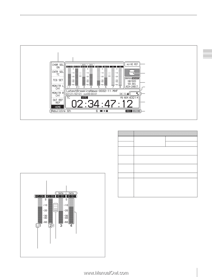
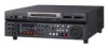
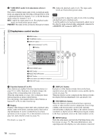
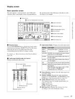
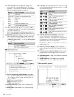
Chapter 2 Names and Functions of Parts Display screen Basic operation screen This unit supports "1-in/1-out mode" and "VTR mode" operation. Parts of the display screen vary depending on the operation mode. The following screen shows 1-in/1out mode, as an example. 1 Function menu 2 Audio input display/audio level meters 3 System information 4 Media status display 5 Recording/playback format 6 Clip information 7 Operation status display 8 Time data display area 9 Status display area a Function menu Use the PAGE/HOME button to display this menu, and to switch between the pages (HOME, P1 to P5) of the menu. Each page has one to six setting items. Press the corresponding function button to change a setting. For details, see "Basic Operations of the Function Menu" (page 45). b Audio input display/audio level meters Displays information about audio. A Input signal display B Data indication F Level bars E Reference level D Audio channel C Monitor channel A Input signal display: Displays the audio input signal. . Display Input signal ANA-1 Analog audio signal Channel 1, 3, 5, 7 ANA-2 Channel 2, 4, 6, 8 AES/EBU AES/EBU format digital audio signal (flashes when there is no input signal) HD-SDI HD-SDI audio signal (flashes when there is no input signal) SD-SDI SD-SDI audio signal (flashes when there is no input signal) SG Test signal from the internal signal generator DVB-ASI DVB-ASI TS signal (flashes when there is no input signal) When the video input signal is set to "DVBASI", A1 INPUT to A8 INPUT are automatically set to "DVB-ASI". B Data indication: Appears when the input signals are non-audio signals. C Monitor channel: Displays the audio monitoring channels set with MONITR L and MONITR R on the HOME page of the function menu (see page 45). D Audio channel: Displays the audio channels. Also indicates preset or variable-speed mode by its color (see page 18). White: Preset mode Green: Variable-speed mode E Reference level: Displays the reference level for recording as set in the maintenance menu. 21 Front Panel
-
 1
1 -
2
-
3
-
4
-
5
-
6
-
7
-
8
-
9
-
10
-
11
-
12
-
13
-
14
-
15
-
 16
16 -
 17
17 -
 18
18 -
 19
19 -
 20
20 -
 21
21 -
 22
22 -
 23
23 -
 24
24 -
 25
25 -
 26
26 -
27
-
28
-
29
-
30
-
31
-
32
-
33
-
34
-
35
-
36
-
37
-
38
-
39
-
40
-
41
-
42
-
43
-
44
-
45
-
46
-
47
-
48
-
49
-
50
-
51
-
52
-
53
-
54
-
55
-
56
-
57
-
58
-
59
-
60
-
61
-
62
-
63
-
64
-
65
-
66
-
67
-
68
-
69
-
70
-
71
-
72
-
73
-
74
-
75
-
76
-
77
-
78
-
79
-
80
-
81
-
82
-
83
-
84
-
85
-
86
-
87
-
88
-
89
-
90
-
91
-
92
-
93
-
94
-
95
-
96
-
97
-
98
-
99
-
100
-
101
-
102
-
103
-
104
-
105
-
106
-
107
-
108
-
109
-
110
-
111
-
112
-
113
-
114
-
115
-
116
-
117
-
118
-
119
-
120
-
121
-
122
-
123
-
124
-
125
-
126
-
127
-
128
-
129
-
130
-
131
-
132
-
133
-
134
-
135
-
136
-
137
-
138
-
139
-
140
-
141
-
142
-
143
-
144
-
145
-
146
-
147
-
148
-
149
-
150
-
151
-
152
-
153
-
154
-
155
-
156
-
157
-
158
-
159
-
160
-
161
 |
 |