Sony XDSPD2000 User Manual (XDS-PD1000 and XDS-PD2000 Operation Manual for Fir - Page 29
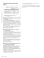
Timecode input/output Power supply Digital audio signal input/output,
 |
View all Sony XDSPD2000 manuals
Add to My Manuals
Save this manual to your list of manuals |
Page 29 highlights
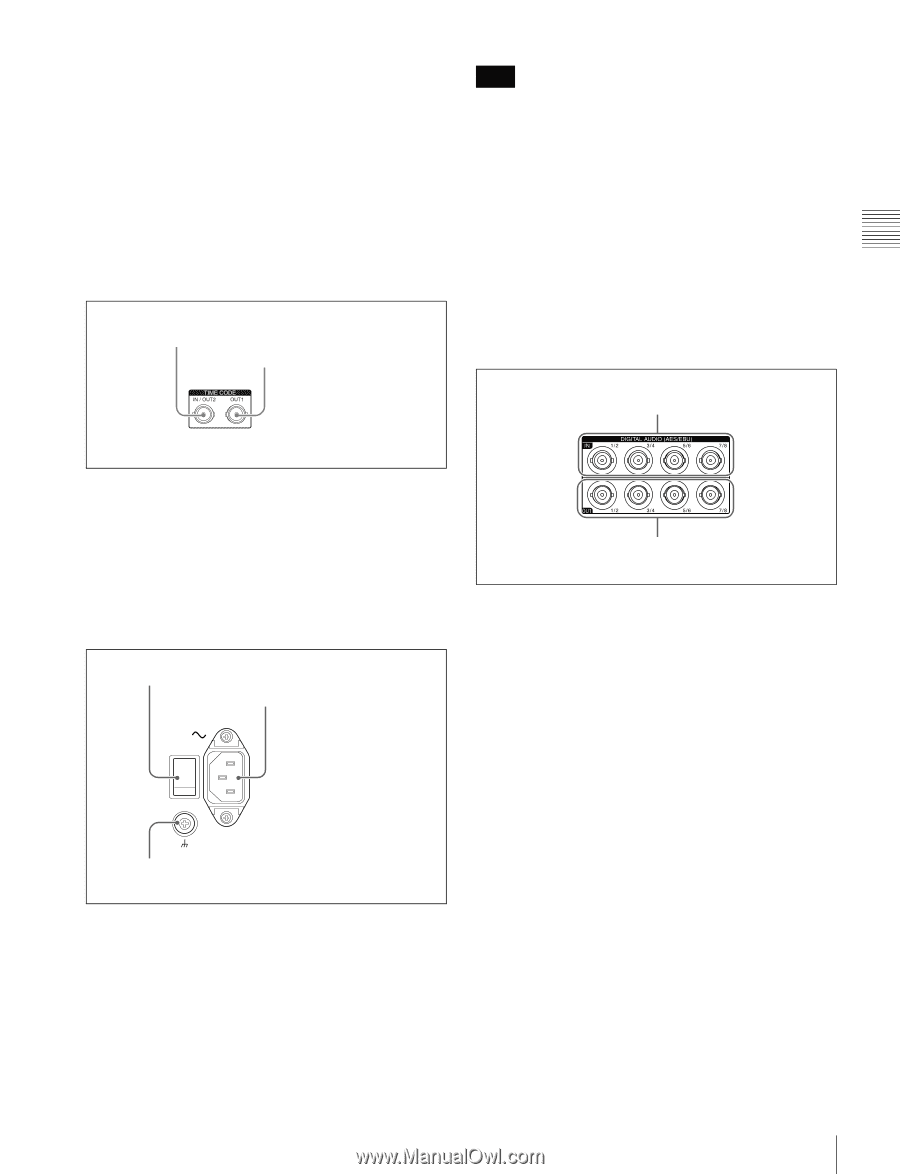
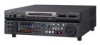
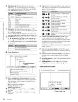
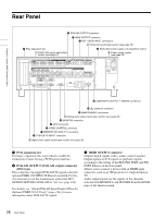
Chapter 2 Names and Functions of Parts the data independent of the setting for CHAR SEL with the setting for setup menu item 027. 1) You can set E-E signal output at all times using setup menu item 156 MONITOR OUT SELECT to REC port. See "Basic Operations of the Function Menu" (page 45) for more information about the CHAR SEL settings. See page 102 for more information about the setup menu item 027 SD CHARACTER. 2 Timecode input/output section Note Before turning the main power off, always check to be sure that the on/standby indicator on the front panel is lit in red (showing that this unit is in the standby state), and then press the main power switch to the off side. b AC power input connector (-) Connect to an AC power supply with the power cord (not supplied). c Ground terminal (U) Connect this to ground as required. 1 TIME CODE IN/OUT2 connector 2 TIME CODE OUT1 connector 4 Digital audio signal input/output section 1 DIGITAL AUDIO (AES/EBU) IN 1/2, 3/4, 5/6, 7/8 connectors a TIME CODE IN/OUT2 connector (BNC type) This inputs an SMPTE timecode signal generated by an external device. b TIME CODE OUT1 connector (BNC type) This outputs playback timecode signal. 3 Power supply section 1 Main power switch 2 AC power input connector 3 Ground terminal 2 DIGITAL AUDIO (AES/EBU) OUT 1/2, 3/4, 5/6, 7/8 connectors a DIGITAL AUDIO (AES/EBU) IN (digital audio input) 1/2, 3/4, 5/6, 7/8 connectors (BNC type) These input AES/EBU format digital audio signals. b DIGITAL AUDIO (AES/EBU) OUT (digital audio output) 1/2, 3/4, 5/6, 7/8 connectors (BNC type) These output AES/EBU format digital audio signals. In VTR mode, the playback signal is output when the unit is playing a clip, and the E-E signal is output when the unit is recording or set to E-E mode. To treat the input and output signals of these connectors as non-audio signals, set the maintenance menu item M37: AUDIO CONFIG >M372: NON-AUDIO INPUT (recording) (see page 123). a Main power switch Press the upper side to power the unit on. Press the lower side to power the unit off. When using the unit, normally leave the main power switch in the on position, and use the on/standby button on the front panel to switch the unit between the operating state and standby state. 29 Rear Panel
-
 1
1 -
2
-
3
-
4
-
5
-
6
-
7
-
8
-
9
-
10
-
11
-
12
-
13
-
14
-
15
-
16
-
17
-
18
-
19
-
20
-
21
-
22
-
23
-
 24
24 -
 25
25 -
 26
26 -
 27
27 -
 28
28 -
 29
29 -
 30
30 -
 31
31 -
 32
32 -
 33
33 -
 34
34 -
35
-
36
-
37
-
38
-
39
-
40
-
41
-
42
-
43
-
44
-
45
-
46
-
47
-
48
-
49
-
50
-
51
-
52
-
53
-
54
-
55
-
56
-
57
-
58
-
59
-
60
-
61
-
62
-
63
-
64
-
65
-
66
-
67
-
68
-
69
-
70
-
71
-
72
-
73
-
74
-
75
-
76
-
77
-
78
-
79
-
80
-
81
-
82
-
83
-
84
-
85
-
86
-
87
-
88
-
89
-
90
-
91
-
92
-
93
-
94
-
95
-
96
-
97
-
98
-
99
-
100
-
101
-
102
-
103
-
104
-
105
-
106
-
107
-
108
-
109
-
110
-
111
-
112
-
113
-
114
-
115
-
116
-
117
-
118
-
119
-
120
-
121
-
122
-
123
-
124
-
125
-
126
-
127
-
128
-
129
-
130
-
131
-
132
-
133
-
134
-
135
-
136
-
137
-
138
-
139
-
140
-
141
-
142
-
143
-
144
-
145
-
146
-
147
-
148
-
149
-
150
-
151
-
152
-
153
-
154
-
155
-
156
-
157
-
158
-
159
-
160
-
161
 |
 |