Sony XDSPD2000 User Manual (XDS-PD1000 and XDS-PD2000 Operation Manual for Fir - Page 22
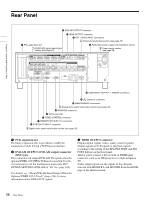
Level bars, System information, Reference signal, INPUT, HD REF, Video input display, HD-SDI, DVB-ASI
 |
View all Sony XDSPD2000 manuals
Add to My Manuals
Save this manual to your list of manuals |
Page 22 highlights
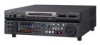
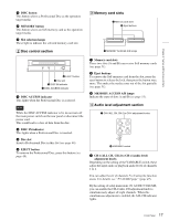
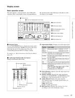
Chapter 2 Names and Functions of Parts F Level bars: Display the audio recording or playback levels of channels 1 to 8. The OVER indicators light when the audio level exceeds 0 dB. c System information A Reference signal B Video input display B Video input display: This displays the selected video input signal. HD-SDI: HD-SDI video input SD-SDI: SD-SDI video input SG: Test video signal from the internal signal generator DVB-ASI 1): DVB-ASI TS signal 1) When the maintenance menu item M22: OPTION SETTING >DVBASI is set to "on" with the optional PDBK-202 being installed (see page 122). A Reference signal: This displays the type of reference signal to which this unit is synchronizing. When there is no display, the unit is synchronizing to the internal reference signal. INPUT: Input video HD REF: HD-format reference signal SD REF: SD-format reference signal The video signal input is selected with V INPUT on page P1 INPUT of the function menu (see page 46). Note The display blinks when there is no video input signal, and when the video input signal does not match the system frequency of this unit. d Media status display Displays the icons in the following table to indicate the status of the selected recording media. Icons Professional Disc Internal storage Memory card PFD23A/ (slot A selected) PFD50DLA/ PFD100TLA PFD128QLW - Status Not loaded Being mounted Normal status Warning level error has occurred (finalizing is impossible) Error has occurred (restoring is impossible. However, restoring is supported using Update/ Restore Media (see page 86)) - Finalized - Being ejected The PFD128QLW media status display changes with the remaining capacity of the recordable resource space (for writing the disc management data, etc.). Icon Yellow bar Status The available recordable resource space is running out. Red bar There is no available recordable resource space on the disc. 22 Front Panel
-
 1
1 -
2
-
3
-
4
-
5
-
6
-
7
-
8
-
9
-
10
-
11
-
12
-
13
-
14
-
15
-
16
-
 17
17 -
 18
18 -
 19
19 -
 20
20 -
 21
21 -
 22
22 -
 23
23 -
 24
24 -
 25
25 -
 26
26 -
 27
27 -
28
-
29
-
30
-
31
-
32
-
33
-
34
-
35
-
36
-
37
-
38
-
39
-
40
-
41
-
42
-
43
-
44
-
45
-
46
-
47
-
48
-
49
-
50
-
51
-
52
-
53
-
54
-
55
-
56
-
57
-
58
-
59
-
60
-
61
-
62
-
63
-
64
-
65
-
66
-
67
-
68
-
69
-
70
-
71
-
72
-
73
-
74
-
75
-
76
-
77
-
78
-
79
-
80
-
81
-
82
-
83
-
84
-
85
-
86
-
87
-
88
-
89
-
90
-
91
-
92
-
93
-
94
-
95
-
96
-
97
-
98
-
99
-
100
-
101
-
102
-
103
-
104
-
105
-
106
-
107
-
108
-
109
-
110
-
111
-
112
-
113
-
114
-
115
-
116
-
117
-
118
-
119
-
120
-
121
-
122
-
123
-
124
-
125
-
126
-
127
-
128
-
129
-
130
-
131
-
132
-
133
-
134
-
135
-
136
-
137
-
138
-
139
-
140
-
141
-
142
-
143
-
144
-
145
-
146
-
147
-
148
-
149
-
150
-
151
-
152
-
153
-
154
-
155
-
156
-
157
-
158
-
159
-
160
-
161
 |
 |
