Yamaha AW2400 Owner's Manual - Page 100
Input channels, Tracks, REMAIN, DIGITAL IN, DIRECT OUT, MULTI CONNECTION ON/OFF button
 |
View all Yamaha AW2400 manuals
Add to My Manuals
Save this manual to your list of manuals |
Page 100 highlights
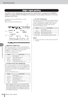
Input signal patching 11 Patching and signal flow B Input channels This area indicates the connection state of input channels 1-16. When you move the cursor to the symbol and press the [ENTER] key, the symbol will be highlighted and the corresponding input channel will be selected as a recording source. C Tracks This area indicates the connection state of tracks 1-24. When you move the cursor to the symbol and press the [ENTER] key, the symbol will be highlighted and the corresponding track will be selected as a recording destination. You can switch a track's mute status on/off by moving the cursor to the number that indicates the track number and pressing the [ENTER] key. D REMAIN This indicates the remaining recordable time. The remaining time will depend on the number of tracks that are enabled for recording. E DIGITAL IN This assigns the [DIGITAL STEREO IN] connector to an input channel. Here you can select from the following items. • 1.2-15.16 ........Assign the signal of the [DIGITAL STEREO IN] connector to a pair of adjacent odd-numbered/even-numbered input channels (1/2-15/16). The [DIGITAL STEREO IN] connector will not be used. The DIGITAL IN setting takes priority over other inputs selected in the Input Select area. When you assign the DIGITAL IN to an input channel, the corresponding input number in the Input Select area will change to a symbol. This indicates that a signal has already been assigned to the corresponding input channel. NOTE • If you enable cascade connection, the digital audio signal received from the [DIGITAL STEREO IN] connector will be sent directly to the stereo bus. While this state exists, the DIGITAL IN field will indicate "ST BUS," and cannot be changed until you disable cascade connection. F DIRECT OUT Here you can select the send position from which the signal of an input channel or track channel is sent to direct output. • PRE FADER The pre-fader signal • POST FADER The post-fader signal G MULTI CONNECTION ON/OFF button If this button is on, you can connect a set of eight input channels and eight tracks in a single operation. H MUTE CLEAR button This button clears the mute status of all tracks. However depending on the bit depth of the song and on the number of tracks that are enabled for recording, there may be cases in which some tracks cannot be unmuted. If so, tracks will be muted consecutively starting with the last-numbered track. I SAFE button When you move the cursor to this button and press the [ENTER] key, all input channel and track channel assignments will be cancelled. This will also execute the MUTE CLEAR (H) operation. HINT • Pressing the [F1] key while holding the Display section [SHIFT] key has the same effect as the SAFE button. 2 Move the cursor to the Input Select field, and use the [DATA/JOG] dial or the [INC]/ [DEC] keys to select the input that will be patched to each input channel. For example if you want mics/instruments connected to [MIC/LINE INPUT] jacks 1-8 to be patched to input channels 1-8, you would make settings as shown below. 3 Move the cursor to the symbol for the record-source input channel, and press the [ENTER] key. The symbol will be highlighted, and the corresponding input channel will be selected as a recording source. The corresponding [INPUT SEL] key (or the [SEL] key of the corresponding input channel) will light red, and the remaining [INPUT SEL] keys (or the [SEL] keys of the remaining input channels) will go dark. If the selected input channel is not yet assigned to a track, all [SEL] keys for the track channels will blink red, indicating that they can be selected as the recording destination. If the selected input channel has already been assigned to a track, only the [SEL] key of the corresponding track channel will blink red. For example if you selected input channel 1 as the recording source, the top panel keys will be as follows. lit flash Tr ack channels (Layer section [TRACK 1-12] key lit) 100 AW2400 Owner's Manual
-
 1
1 -
2
-
3
-
4
-
5
-
6
-
7
-
8
-
9
-
10
-
11
-
12
-
13
-
14
-
15
-
16
-
17
-
18
-
19
-
20
-
21
-
22
-
23
-
24
-
25
-
26
-
27
-
28
-
29
-
30
-
31
-
32
-
33
-
34
-
35
-
36
-
37
-
38
-
39
-
40
-
41
-
42
-
43
-
44
-
45
-
46
-
47
-
48
-
49
-
50
-
51
-
52
-
53
-
54
-
55
-
56
-
57
-
58
-
59
-
60
-
61
-
62
-
63
-
64
-
65
-
66
-
67
-
68
-
69
-
70
-
71
-
72
-
73
-
74
-
75
-
76
-
77
-
78
-
79
-
80
-
81
-
82
-
83
-
84
-
85
-
86
-
87
-
88
-
89
-
90
-
91
-
92
-
93
-
94
-
 95
95 -
 96
96 -
 97
97 -
 98
98 -
 99
99 -
 100
100 -
 101
101 -
 102
102 -
 103
103 -
 104
104 -
 105
105 -
106
-
107
-
108
-
109
-
110
-
111
-
112
-
113
-
114
-
115
-
116
-
117
-
118
-
119
-
120
-
121
-
122
-
123
-
124
-
125
-
126
-
127
-
128
-
129
-
130
-
131
-
132
-
133
-
134
-
135
-
136
-
137
-
138
-
139
-
140
-
141
-
142
-
143
-
144
-
145
-
146
-
147
-
148
-
149
-
150
-
151
-
152
-
153
-
154
-
155
-
156
-
157
-
158
-
159
-
160
-
161
-
162
-
163
-
164
-
165
-
166
-
167
-
168
-
169
-
170
-
171
-
172
-
173
-
174
-
175
-
176
-
177
-
178
-
179
-
180
-
181
-
182
-
183
-
184
-
185
-
186
-
187
-
188
-
189
-
190
-
191
-
192
-
193
-
194
-
195
-
196
-
197
-
198
-
199
-
200
-
201
-
202
-
203
-
204
-
205
-
206
-
207
-
208
-
209
-
210
-
211
-
212
-
213
-
214
-
215
-
216
-
217
-
218
-
219
-
220
-
221
-
222
-
223
-
224
-
225
-
226
-
227
-
228
-
229
-
230
-
231
-
232
-
233
-
234
-
235
-
236
-
237
-
238
-
239
-
240
-
241
-
242
-
243
-
244
-
245
-
246
-
247
-
248
-
249
-
250
-
251
-
252
-
253
-
254
-
255
-
256
-
257
-
258
-
259
-
260
-
261
-
262
-
263
-
264
-
265
-
266
-
267
-
268
-
269
-
270
-
271
-
272
-
273
-
274
-
275
-
276
-
277
-
278
-
279
-
280
-
281
-
282
-
283
-
284
-
285
-
286
-
287
-
288
 |
 |
