Yamaha AW2400 Owner's Manual - Page 151
Dynamics Processing, Using the Gates
 |
View all Yamaha AW2400 manuals
Add to My Manuals
Save this manual to your list of manuals |
Page 151 highlights
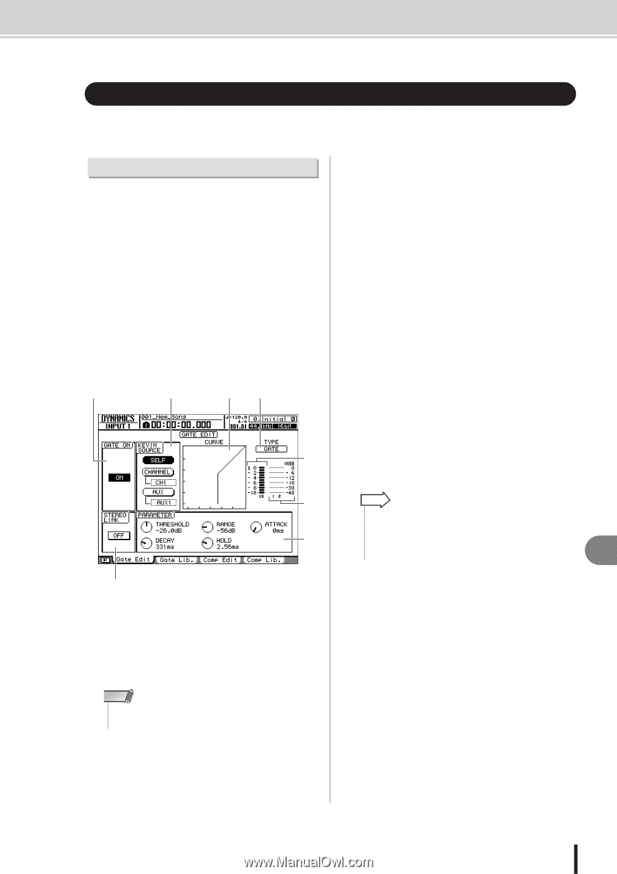
Dynamics Processing Dynamics Processing The AW2400 provides gate and compressor facilities for dynamics processing. In this section operation of the gate and compressor will be explained individually. Using the Gates The gate attenuates signals below a specified threshold level, and can be used to eliminate noise in silent sections of a track. Gates are only provided on input channels. 1 Use the Layer section, [INPUT SEL] and [SEL] keys to select the channel to which the gate is to be applied. 2 Press the Selected Channel section [DYN] key so that its indicator lights, then press Selected Channel knob 1, 2, 3, or 4. The DYNAMICS screen will appear. 3 Press the Display section [F1] key, or press the [DYN] key as many times as necessary until the Gate Edit page appears. A C DE F G H B The Gate Edit Page includes the following items. 1 GATE ON/OFF button Switches the gate on/off. B STEREO LINK button Turning this button on links gate operation for paired channels. NOTE • Gate operation can only be linked for adjacent odd and even numbered channels that can be paired. C KEYIN SOURCE field Selects one of the following trigger sources for the gate. • SELF button ... Selects the signal from the currently selected channel. • CHANNEL button Selects the signal from the channel specified in the box below the button (CH1-CH16). After selecting a channel in the channel box, press the [ENTER] key to confirm the selection. • AUX button..... Selects the signal from the AUX send specified in the box below the button (AUX1-AUX4). After selecting an AUX send in the box, press the [ENTER] key to confirm the selection. D Response curve This graph indicates the approximate response of the gate settings. The horizontal axis of the graph is the input level, and the vertical axis is the output level. E TYPE Indicates the currently selected gate type. The displayed indication has the following meaning. • GATE Gate • DUCKING........ Ducking HINT • You cannot change the gate type via this page. If you want to use a different gate type, you must recall a library setting that uses the desired type. For details on recalling library gate settings, refer to "EQ/Dynamics Processor Library Operation" on page 154. F GR (Gain Reduction) Indicates the amount of gain reduction produced by the gate processor over a range of -18 dB to 0 dB. G Output meter Indicates the level of the signal after it has passed through the gate processor. H PARAMETER Here you can edit the parameters of the gate processor. The type of parameters and their ranges will differ depending on the gate type. For details on the types of parameter and their function, refer to the appendix. 16 Pan, EQ, and Dynamics Processing AW2400 Owner's Manual 151
-
 1
1 -
2
-
3
-
4
-
5
-
6
-
7
-
8
-
9
-
10
-
11
-
12
-
13
-
14
-
15
-
16
-
17
-
18
-
19
-
20
-
21
-
22
-
23
-
24
-
25
-
26
-
27
-
28
-
29
-
30
-
31
-
32
-
33
-
34
-
35
-
36
-
37
-
38
-
39
-
40
-
41
-
42
-
43
-
44
-
45
-
46
-
47
-
48
-
49
-
50
-
51
-
52
-
53
-
54
-
55
-
56
-
57
-
58
-
59
-
60
-
61
-
62
-
63
-
64
-
65
-
66
-
67
-
68
-
69
-
70
-
71
-
72
-
73
-
74
-
75
-
76
-
77
-
78
-
79
-
80
-
81
-
82
-
83
-
84
-
85
-
86
-
87
-
88
-
89
-
90
-
91
-
92
-
93
-
94
-
95
-
96
-
97
-
98
-
99
-
100
-
101
-
102
-
103
-
104
-
105
-
106
-
107
-
108
-
109
-
110
-
111
-
112
-
113
-
114
-
115
-
116
-
117
-
118
-
119
-
120
-
121
-
122
-
123
-
124
-
125
-
126
-
127
-
128
-
129
-
130
-
131
-
132
-
133
-
134
-
135
-
136
-
137
-
138
-
139
-
140
-
141
-
142
-
143
-
144
-
145
-
 146
146 -
 147
147 -
 148
148 -
 149
149 -
 150
150 -
 151
151 -
 152
152 -
 153
153 -
 154
154 -
 155
155 -
 156
156 -
157
-
158
-
159
-
160
-
161
-
162
-
163
-
164
-
165
-
166
-
167
-
168
-
169
-
170
-
171
-
172
-
173
-
174
-
175
-
176
-
177
-
178
-
179
-
180
-
181
-
182
-
183
-
184
-
185
-
186
-
187
-
188
-
189
-
190
-
191
-
192
-
193
-
194
-
195
-
196
-
197
-
198
-
199
-
200
-
201
-
202
-
203
-
204
-
205
-
206
-
207
-
208
-
209
-
210
-
211
-
212
-
213
-
214
-
215
-
216
-
217
-
218
-
219
-
220
-
221
-
222
-
223
-
224
-
225
-
226
-
227
-
228
-
229
-
230
-
231
-
232
-
233
-
234
-
235
-
236
-
237
-
238
-
239
-
240
-
241
-
242
-
243
-
244
-
245
-
246
-
247
-
248
-
249
-
250
-
251
-
252
-
253
-
254
-
255
-
256
-
257
-
258
-
259
-
260
-
261
-
262
-
263
-
264
-
265
-
266
-
267
-
268
-
269
-
270
-
271
-
272
-
273
-
274
-
275
-
276
-
277
-
278
-
279
-
280
-
281
-
282
-
283
-
284
-
285
-
286
-
287
-
288
 |
 |