Yamaha AW2400 Owner's Manual - Page 104
Output signal patching, OMNI OUT ASSIGN field
 |
View all Yamaha AW2400 manuals
Add to My Manuals
Save this manual to your list of manuals |
Page 104 highlights
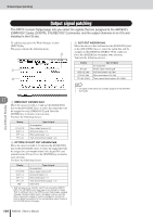
Output signal patching Output signal patching The PATCH screen Output page lets you select the signals that are assigned to the AW2400's [OMNI OUT] jacks, [DIGITAL STEREO OUT] connector, and the output channels of an I/O card installed in the I/O slot. To call this page press the Work Navigate section [PATCH] key. This page contains the following items. C A B C D.ST OUT ASSIGN field Move the cursor to this field and use the [DATA/JOG] dial or the [INC]/[DEC] keys to select the signal that will be assigned to the [DIGITAL STEREO OUT] connector. Press the [ENTER] key to finalize your selection. You have the following choices. Display --- ST L&R AUX 1&2, 3&4 EFF 1&2, 3&4 TR 1&2-23&24 Type of signal No assignment Stereo output channel L&R AUX send master 1&2, 3&4 Effect send master 1&2, 3&4 Track channel direct outputs 1&2-23&24 HINT • The signal of the stereo bus is always assigned to the [STEREO OUT] jacks. 11 Patching and signal flow 1 OMNI OUT ASSIGN field Move the cursor to fields 1-4 and use the [DATA/JOG] dial or the [INC]/[DEC] keys to select the signal that will be assigned to each [OMNI OUT] jack. Press the [ENTER] key to finalize your selection. You have the following choices. Display --- ST L/ST R AUX 1-4 EFF 1-4 TR 1-24 Type of signal No assignment Stereo output channel L/R AUX send master 1-4 Effect send master 1-4 Track channel direct outputs 1-24 B OPTION I/O SLOT OUT ASSIGN field Move the cursor to fields 1-16 and use the [DATA/JOG] dial or the [INC]/[DEC] keys to select the signal that will be assigned to each output channel of a digital I/O card installed in the I/O slot. Press the [ENTER] key to finalize your selection. You have the following choices. Display --- ST L/ST R AUX 1-4 EFF 1-4 TR 1-24 INS*1 Type of signal No assignment Stereo output channel L/R AUX send master 1-4 Effect send master 1-4 Track channel direct outputs 1-24 Insert send *1. "INS" will appear only if SLOT1-SLOT16 is selected for INSERT EFF in the CH VIEW screen View page. If you attempt to change "INS" to a different item in the PATCH screen Output page, a popup message ("Used As Effect Insert!") will appear, and you won't be able to execute the change. In order to change this, you will first have to defeat the selection for the corresponding output channel in the CH VIEW screen View page. 104 AW2400 Owner's Manual
-
 1
1 -
2
-
3
-
4
-
5
-
6
-
7
-
8
-
9
-
10
-
11
-
12
-
13
-
14
-
15
-
16
-
17
-
18
-
19
-
20
-
21
-
22
-
23
-
24
-
25
-
26
-
27
-
28
-
29
-
30
-
31
-
32
-
33
-
34
-
35
-
36
-
37
-
38
-
39
-
40
-
41
-
42
-
43
-
44
-
45
-
46
-
47
-
48
-
49
-
50
-
51
-
52
-
53
-
54
-
55
-
56
-
57
-
58
-
59
-
60
-
61
-
62
-
63
-
64
-
65
-
66
-
67
-
68
-
69
-
70
-
71
-
72
-
73
-
74
-
75
-
76
-
77
-
78
-
79
-
80
-
81
-
82
-
83
-
84
-
85
-
86
-
87
-
88
-
89
-
90
-
91
-
92
-
93
-
94
-
95
-
96
-
97
-
98
-
 99
99 -
 100
100 -
 101
101 -
 102
102 -
 103
103 -
 104
104 -
 105
105 -
 106
106 -
 107
107 -
 108
108 -
 109
109 -
110
-
111
-
112
-
113
-
114
-
115
-
116
-
117
-
118
-
119
-
120
-
121
-
122
-
123
-
124
-
125
-
126
-
127
-
128
-
129
-
130
-
131
-
132
-
133
-
134
-
135
-
136
-
137
-
138
-
139
-
140
-
141
-
142
-
143
-
144
-
145
-
146
-
147
-
148
-
149
-
150
-
151
-
152
-
153
-
154
-
155
-
156
-
157
-
158
-
159
-
160
-
161
-
162
-
163
-
164
-
165
-
166
-
167
-
168
-
169
-
170
-
171
-
172
-
173
-
174
-
175
-
176
-
177
-
178
-
179
-
180
-
181
-
182
-
183
-
184
-
185
-
186
-
187
-
188
-
189
-
190
-
191
-
192
-
193
-
194
-
195
-
196
-
197
-
198
-
199
-
200
-
201
-
202
-
203
-
204
-
205
-
206
-
207
-
208
-
209
-
210
-
211
-
212
-
213
-
214
-
215
-
216
-
217
-
218
-
219
-
220
-
221
-
222
-
223
-
224
-
225
-
226
-
227
-
228
-
229
-
230
-
231
-
232
-
233
-
234
-
235
-
236
-
237
-
238
-
239
-
240
-
241
-
242
-
243
-
244
-
245
-
246
-
247
-
248
-
249
-
250
-
251
-
252
-
253
-
254
-
255
-
256
-
257
-
258
-
259
-
260
-
261
-
262
-
263
-
264
-
265
-
266
-
267
-
268
-
269
-
270
-
271
-
272
-
273
-
274
-
275
-
276
-
277
-
278
-
279
-
280
-
281
-
282
-
283
-
284
-
285
-
286
-
287
-
288
 |
 |
