Yamaha AW2400 Owner's Manual - Page 199
Yamaha AW2400 Manual
 |
View all Yamaha AW2400 manuals
Add to My Manuals
Save this manual to your list of manuals |
Page 199 highlights
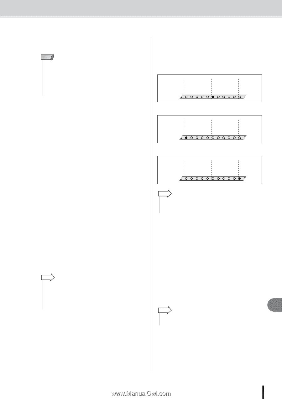
MIDI Synchronization Message Setup E DEVICE NO. box Specifies the MMC device number (1-127) that the AW2400 will receive. NOTE • The MMC device number is an identifying number used to distinguish devices that transmit and receive MMC commands. When using MMC, the AW2400 and the external MIDI device must be set to the same MMC device number. • When transmitting MMC data from the AW2400, the MMC device number is always set to "128" (allowing control of all MMC-compatible devices). F MTC field Specifies how the AW2400 operates when synchronized with an external MIDI device using MTC (MIDI Time Code). G MTC MASTER button When this button is on the AW2400 functions as MTC master. Turn this button on when you want external equipment to synchronize to the AW2400. H MTC SLAVE button When this button is turned on the AW2400 functions as MTC slave, and will follow MTC received via the MIDI IN connector (or USB connector or digital I/O card input port). Turn this button on when you want to synchronize two AW2400 units, or synchronize the AW2400 to an external device that can only function in MTC master mode. I SYNC AVERAGE box Select one of the following to specify how closely the AW2400 will follow the incoming MTC data when functioning as an MTC slave. • 0 The AW2400 will synchronize to the incoming MTC data with the highest precision. If the incoming MTC has significant instability, synchronization may be interrupted or become unreliable with this setting. • 1 This setting provides more tolerance to MTC instability than the OFF setting. • 2 This setting allows the maximum tolerance. Use this setting if the MTC master is an external MIDI device that has significant instability. HINT • If the accuracy of the incoming MTC becomes unstable when the AW2400 is functioning as an MTC slave and is synchronized to an external MIDI device, the AW2400 will make slight adjustments in playback pitch in an attempt to maintain synchronization. The SYNC AVERAGE parameter specifies the range of MTC variance that will be tolerated. J OFFSET When using the AW2400 as an MTC slave, this parameter shifts the absolute time of the AW2400 forward or backward relative to the incoming MTC. The range is -24:00:00:00.00 to +24:00:00:00.00. OFFSET = 00:00:00:00.00 Incoming time code 00:00:10:00.00 Time code 00:00:10:00.00 display (ABS) Song 00:00:15:00.00 00:00:15:00.00 00:00:20:00.00 00:00:20:00.00 OFFSET = +00:00:05:00.00 Incoming time code 00:00:10:00.00 Time code 00:00:15:00.00 display (ABS) Song 00:00:15:00.00 00:00:20:00.00 00:00:20:00.00 00:00:25:00.00 OFFSET = -00:00:05:00.00 Incoming time 00:00:10:00.00 code Time code 00:00:05:00.00 display (ABS) Song 00:00:15:00.00 00:00:10:00.00 00:00:20:00.00 00:00:15:00.00 HINT • The OFFSET setting has no effect on MTC output via the MIDI OUT/THRU connector (or USB connector or digital I/O card output port). K SYNC OUT field Selects the type of MIDI message to be used for synchronization. • OFF button ........Engage this button (it will appear inverted) to disable transmission of MIDI synchronization messages. • MTC button .......When this button is ON MTC will be transmitted while the recorder is running. • MIDI CLOCK Button When this button is ON the MIDI clock will be transmitted while the recorder is running. Also, appropriate START, STOP, CONTINUE and SONG POSITION messages will be transmitted when the transport is operated. HINT • MIDI clock operation is based on the tempo specified in the Tempo Map (refer to page 175 for Tempo Map setup details). 20 MIDI AW2400 Owner's Manual 199
-
 1
1 -
2
-
3
-
4
-
5
-
6
-
7
-
8
-
9
-
10
-
11
-
12
-
13
-
14
-
15
-
16
-
17
-
18
-
19
-
20
-
21
-
22
-
23
-
24
-
25
-
26
-
27
-
28
-
29
-
30
-
31
-
32
-
33
-
34
-
35
-
36
-
37
-
38
-
39
-
40
-
41
-
42
-
43
-
44
-
45
-
46
-
47
-
48
-
49
-
50
-
51
-
52
-
53
-
54
-
55
-
56
-
57
-
58
-
59
-
60
-
61
-
62
-
63
-
64
-
65
-
66
-
67
-
68
-
69
-
70
-
71
-
72
-
73
-
74
-
75
-
76
-
77
-
78
-
79
-
80
-
81
-
82
-
83
-
84
-
85
-
86
-
87
-
88
-
89
-
90
-
91
-
92
-
93
-
94
-
95
-
96
-
97
-
98
-
99
-
100
-
101
-
102
-
103
-
104
-
105
-
106
-
107
-
108
-
109
-
110
-
111
-
112
-
113
-
114
-
115
-
116
-
117
-
118
-
119
-
120
-
121
-
122
-
123
-
124
-
125
-
126
-
127
-
128
-
129
-
130
-
131
-
132
-
133
-
134
-
135
-
136
-
137
-
138
-
139
-
140
-
141
-
142
-
143
-
144
-
145
-
146
-
147
-
148
-
149
-
150
-
151
-
152
-
153
-
154
-
155
-
156
-
157
-
158
-
159
-
160
-
161
-
162
-
163
-
164
-
165
-
166
-
167
-
168
-
169
-
170
-
171
-
172
-
173
-
174
-
175
-
176
-
177
-
178
-
179
-
180
-
181
-
182
-
183
-
184
-
185
-
186
-
187
-
188
-
189
-
190
-
191
-
192
-
193
-
 194
194 -
 195
195 -
 196
196 -
 197
197 -
 198
198 -
 199
199 -
 200
200 -
 201
201 -
 202
202 -
 203
203 -
 204
204 -
205
-
206
-
207
-
208
-
209
-
210
-
211
-
212
-
213
-
214
-
215
-
216
-
217
-
218
-
219
-
220
-
221
-
222
-
223
-
224
-
225
-
226
-
227
-
228
-
229
-
230
-
231
-
232
-
233
-
234
-
235
-
236
-
237
-
238
-
239
-
240
-
241
-
242
-
243
-
244
-
245
-
246
-
247
-
248
-
249
-
250
-
251
-
252
-
253
-
254
-
255
-
256
-
257
-
258
-
259
-
260
-
261
-
262
-
263
-
264
-
265
-
266
-
267
-
268
-
269
-
270
-
271
-
272
-
273
-
274
-
275
-
276
-
277
-
278
-
279
-
280
-
281
-
282
-
283
-
284
-
285
-
286
-
287
-
288
 |
 |