Yamaha AW2400 Owner's Manual - Page 107
Ecomp Fon/off, Lvl Knob Ginsert Eff Hpan/bal Knob Ibus1, Bus2, St Jrec Tr Klevel Meter Laux, Effect
 |
View all Yamaha AW2400 manuals
Add to My Manuals
Save this manual to your list of manuals |
Page 107 highlights
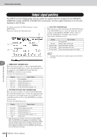
Displaying the mix parameters for individual channels E COMP Move the cursor to the symbol below COMP and press the [ENTER] key to turn the compressor for that channel on or off or select the compressor insert point. Press the [ENTER] key repeatedly to sequentially select the following insert points. A Before the channel EQ B Before the channel fader C After the channel fader D Compressor off To A Refer to "Using the Compressors" on page 152 for details. HINT • You can move the cursor to the insert point and press the [ENTER] key to reverse the order of the COMP and an INSERT EFF. NOTE • Since no EQ is provided on the effect send master channels, the compressor can be inserted either pre-fader or post-fader. F ON/OFF, LVL knob • ON/OFF ..........Move the cursor to this position and press the [ENTER] key to turn the channel on or off. This function is linked to the channel [ON] keys. • LVL knob ........Move the cursor to this knob and use the [DATA/JOG] dial or [INC]/[DEC] keys to adjust the channel level. This function is linked to the channel faders. G INSERT EFF This parameter is used to insert an internal effect to a specified point in the channel, or to specify an insert point for insertion of an external effect. If you move the cursor to the field to the right of INSERT EFF and press the [ENTER] key, a popup window will appear allowing selection of an internal effect or I/O channel on an optional I/O card. HINT • For details on insert effect operation refer to "Inserting an Effect Into a Channel" on page 119. • When SLOT1-16 is selected the specified channel insert point is assigned to the corresponding channel on an optional I/O card installed in the AW2400. This assignment is shown in the PATCH screen Output page OPTION I/O SLOT OUT ASSIGN field. • You can move the cursor to the insert point and press the [ENTER] key to reverse the order of the COMP and an INSERT EFF. H PAN/BAL knob Move the cursor to this knob and use the [DATA/JOG] dial or [INC]/[DEC] keys to pan the channel signal to the stereo bus or bus 1 and bus 2 (for stereo input channels this functions as a balance control). The effect return channel L and R signals can be adjusted individually. These knobs are linked to the PAN/EQ screen knobs (→ p. 147). I BUS1, BUS2, ST Move the cursor to any of these points and press the [ENTER] key to turn assignment of the channel signal to the corresponding bus - bus 1, bus 2, or stereo bus - on or off. J REC TR Displays the input channel to track assignment, as specified in the RECORD screen Direct page. K Level meter The level meters display input channel, track channel and effect return channel input levels, as well as stereo output channel, bus master channel, AUX send master channel, effect send master channel output levels. L AUX, EFFECT Move the cursor to the appropriate knob and use the [DATA/JOG] dial or [INC]/[DEC] keys to adjust send levels to AUX bus 1-4 or effect bus 1-4 over a range of from - ∞ to +10dB. You can also move the cursor to one of these knobs and press the [ENTER] key to turn the corresponding send off. Further, if you move the cursor to the signal path above the knob and press the [ENTER] key you can switch between pre-fader (PRE) and post-fader (POST) send. These functions are linked to the AUX and EFFECT screens (→ p. 111, 115). NOTE • Signals cannot be sent to the effect buses from an effect return channel. Channel Operation 12 AW2400 Owner's Manual 107
-
 1
1 -
2
-
3
-
4
-
5
-
6
-
7
-
8
-
9
-
10
-
11
-
12
-
13
-
14
-
15
-
16
-
17
-
18
-
19
-
20
-
21
-
22
-
23
-
24
-
25
-
26
-
27
-
28
-
29
-
30
-
31
-
32
-
33
-
34
-
35
-
36
-
37
-
38
-
39
-
40
-
41
-
42
-
43
-
44
-
45
-
46
-
47
-
48
-
49
-
50
-
51
-
52
-
53
-
54
-
55
-
56
-
57
-
58
-
59
-
60
-
61
-
62
-
63
-
64
-
65
-
66
-
67
-
68
-
69
-
70
-
71
-
72
-
73
-
74
-
75
-
76
-
77
-
78
-
79
-
80
-
81
-
82
-
83
-
84
-
85
-
86
-
87
-
88
-
89
-
90
-
91
-
92
-
93
-
94
-
95
-
96
-
97
-
98
-
99
-
100
-
101
-
 102
102 -
 103
103 -
 104
104 -
 105
105 -
 106
106 -
 107
107 -
 108
108 -
 109
109 -
 110
110 -
 111
111 -
 112
112 -
113
-
114
-
115
-
116
-
117
-
118
-
119
-
120
-
121
-
122
-
123
-
124
-
125
-
126
-
127
-
128
-
129
-
130
-
131
-
132
-
133
-
134
-
135
-
136
-
137
-
138
-
139
-
140
-
141
-
142
-
143
-
144
-
145
-
146
-
147
-
148
-
149
-
150
-
151
-
152
-
153
-
154
-
155
-
156
-
157
-
158
-
159
-
160
-
161
-
162
-
163
-
164
-
165
-
166
-
167
-
168
-
169
-
170
-
171
-
172
-
173
-
174
-
175
-
176
-
177
-
178
-
179
-
180
-
181
-
182
-
183
-
184
-
185
-
186
-
187
-
188
-
189
-
190
-
191
-
192
-
193
-
194
-
195
-
196
-
197
-
198
-
199
-
200
-
201
-
202
-
203
-
204
-
205
-
206
-
207
-
208
-
209
-
210
-
211
-
212
-
213
-
214
-
215
-
216
-
217
-
218
-
219
-
220
-
221
-
222
-
223
-
224
-
225
-
226
-
227
-
228
-
229
-
230
-
231
-
232
-
233
-
234
-
235
-
236
-
237
-
238
-
239
-
240
-
241
-
242
-
243
-
244
-
245
-
246
-
247
-
248
-
249
-
250
-
251
-
252
-
253
-
254
-
255
-
256
-
257
-
258
-
259
-
260
-
261
-
262
-
263
-
264
-
265
-
266
-
267
-
268
-
269
-
270
-
271
-
272
-
273
-
274
-
275
-
276
-
277
-
278
-
279
-
280
-
281
-
282
-
283
-
284
-
285
-
286
-
287
-
288
 |
 |
