Yamaha AW2400 Owner's Manual - Page 257
M.BAND DYNA., This is a 2-in/2-out gate that attenuates signals below the specified threshold level.
 |
View all Yamaha AW2400 manuals
Add to My Manuals
Save this manual to your list of manuals |
Page 257 highlights
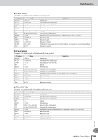
Effects Parameters ■ GATE This is a 2-in/2-out gate that attenuates signals below the specified threshold level. Parameter GATE ON THRESH RANGE ATTACK DECAY HOLD Range ON, OFF -54 to 0 dB -70 to 0 dB 0-120 ms *1 *2 Description Turns the gate function on or off. Sets the threshold level at which the gate begins to affect the input signal. Sets the level when the gate is closed. Sets the time it take for the gate to actually open after the threshold level is exceeded. Sets the time it takes for the gate to close completely after it begins closing. Sets the time it takes for the gate to begin closing after the signal drops below the threshold level. *1. 6-46.0 s (fs=44.1kHz), 5-42.3 s (fs=48kHz) *2. 0.02-2.13 s (fs=44.1kHz), 0.02-1.96 s (fs=48kHz) ■ M.BAND DYNA. Two input, two output 3-band dynamics processor, with individual solo and gain reduction metering for each band. Parameter LOW GAIN MID GAIN HI. GAIN Range -96.0 to +12.0 dB -96.0 to +12.0 dB -96.0 to +12.0 dB PRESENCE -10 to +10 CMP. THRE CMP. RAT CMP. ATK CMP. REL CMP. KNEE LOOKUP CMP. BYP L-M XOVR M-H XOVR SLOPE CEILING EXP. THRE EXP. RAT EXP. REL EXP. BYP LIM. THRE LIM. ATK LIM. REL LIM. BYP LIM. KNEE SOLO LOW SOLO MID SOLO HIGH 24.0 to 0.0 dB 1:1 to 20:1 0-120 ms *1 0-5 0.0-100.0 ms OFF, ON 21.2 Hz-8.00 kHz 21.2 Hz-8.00 kHz -6 to -12 dB -6.0 to 0.0 dB, OFF -54.0 to -24.0 dB 1:1 to ∞:1 *1 OFF, ON -12.0 to 0.0 dB 0-120 ms *1 OFF, ON 0-5 OFF, ON OFF, ON OFF, ON Description Low band level Mid band level High band level For positive values, the threshold of the high band is lowered and the threshold of the low band is increased. For negative values, the opposite will occur. When set to 0, all three bands are affected the same. Compressor threshold Compressor ratio Compressor attack Compressor release time Compressor knee Lookup delay Compressor bypass Low/mid crossover frequency Mid/high crossover frequency Filter slope Specifies the maximum output level Expander threshold Expander ratio Expander release time Expander bypass Limiter threshold Limiter attack Limiter release time Limiter bypass Limiter knee If this is on, only the low-frequency band will be output. If this is on, only the mid-frequency band will be output. If this is on, only the high-frequency band will be output. *1. 6 ms-46.0 s (fs=44.1 kHz), 5 ms-42.3 s (fs=48 kHz) Appendix AW2400 Owner's Manual 257
-
 1
1 -
2
-
3
-
4
-
5
-
6
-
7
-
8
-
9
-
10
-
11
-
12
-
13
-
14
-
15
-
16
-
17
-
18
-
19
-
20
-
21
-
22
-
23
-
24
-
25
-
26
-
27
-
28
-
29
-
30
-
31
-
32
-
33
-
34
-
35
-
36
-
37
-
38
-
39
-
40
-
41
-
42
-
43
-
44
-
45
-
46
-
47
-
48
-
49
-
50
-
51
-
52
-
53
-
54
-
55
-
56
-
57
-
58
-
59
-
60
-
61
-
62
-
63
-
64
-
65
-
66
-
67
-
68
-
69
-
70
-
71
-
72
-
73
-
74
-
75
-
76
-
77
-
78
-
79
-
80
-
81
-
82
-
83
-
84
-
85
-
86
-
87
-
88
-
89
-
90
-
91
-
92
-
93
-
94
-
95
-
96
-
97
-
98
-
99
-
100
-
101
-
102
-
103
-
104
-
105
-
106
-
107
-
108
-
109
-
110
-
111
-
112
-
113
-
114
-
115
-
116
-
117
-
118
-
119
-
120
-
121
-
122
-
123
-
124
-
125
-
126
-
127
-
128
-
129
-
130
-
131
-
132
-
133
-
134
-
135
-
136
-
137
-
138
-
139
-
140
-
141
-
142
-
143
-
144
-
145
-
146
-
147
-
148
-
149
-
150
-
151
-
152
-
153
-
154
-
155
-
156
-
157
-
158
-
159
-
160
-
161
-
162
-
163
-
164
-
165
-
166
-
167
-
168
-
169
-
170
-
171
-
172
-
173
-
174
-
175
-
176
-
177
-
178
-
179
-
180
-
181
-
182
-
183
-
184
-
185
-
186
-
187
-
188
-
189
-
190
-
191
-
192
-
193
-
194
-
195
-
196
-
197
-
198
-
199
-
200
-
201
-
202
-
203
-
204
-
205
-
206
-
207
-
208
-
209
-
210
-
211
-
212
-
213
-
214
-
215
-
216
-
217
-
218
-
219
-
220
-
221
-
222
-
223
-
224
-
225
-
226
-
227
-
228
-
229
-
230
-
231
-
232
-
233
-
234
-
235
-
236
-
237
-
238
-
239
-
240
-
241
-
242
-
243
-
244
-
245
-
246
-
247
-
248
-
249
-
250
-
251
-
 252
252 -
 253
253 -
 254
254 -
 255
255 -
 256
256 -
 257
257 -
 258
258 -
 259
259 -
 260
260 -
 261
261 -
 262
262 -
263
-
264
-
265
-
266
-
267
-
268
-
269
-
270
-
271
-
272
-
273
-
274
-
275
-
276
-
277
-
278
-
279
-
280
-
281
-
282
-
283
-
284
-
285
-
286
-
287
-
288
 |
 |
