Yamaha AW2400 Owner's Manual - Page 99
Patching and signal flow, Input signal patching, Patching for Direct Recording,
 |
View all Yamaha AW2400 manuals
Add to My Manuals
Save this manual to your list of manuals |
Page 99 highlights
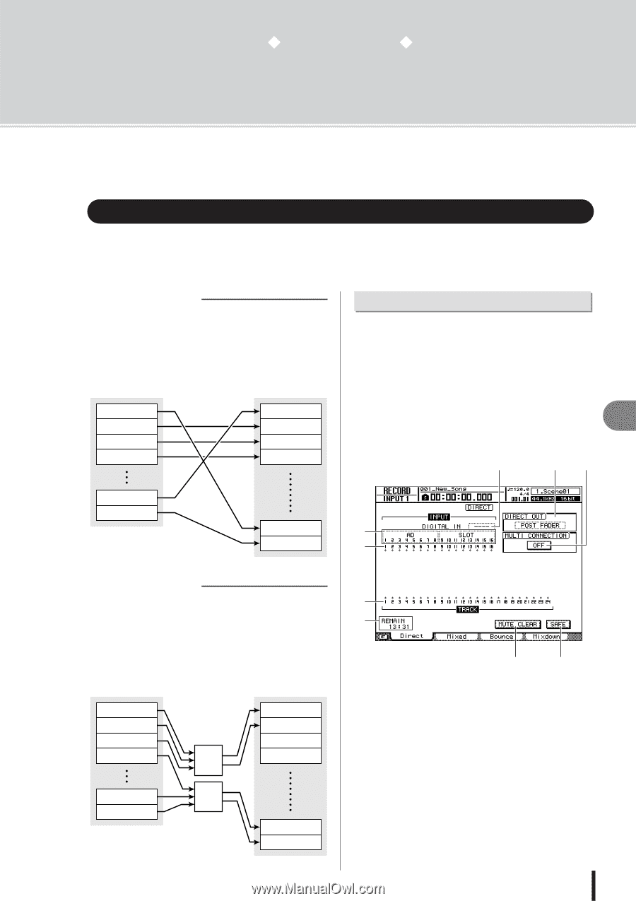
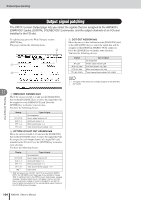
Chapter 11 Patching and signal flow This chapter explains patching and channel signal flow. Input signal patching To record a mic or instrument connected to the AW2400, you can use either of two recording methods; Direct Recording or Mixed Recording. The patching method will depend on the recording method you use. ■ Direct Recording With this method only one input channel is assigned to each recorder track. Although direct recording requires the same number of tracks as the number of input channels you use, it has the advantage that you will be free to adjust the volume, pan (stereo position), and EQ of each track after it has been recorded. Input channel 1 Input channel 2 Input channel 3 Input channel 4 Audio track 1 Audio track 2 Audio track 3 Audio track 4 Patching for Direct Recording This section explains how to patch the signals of input channels to tracks when you're using the Direct Recording method. 1 Call the RECORD screen Direct page by either pressing the Quick Navigate section [RECORD] key as many times as necessary, or by pressing the [F1] key after pressing the [RECORD] key. 11 This page contains the following items. E FG Patching and signal flow Input channel 15 Input channel 16 Audio track 23 A Audio track 24 B ■ Mixed Recording With this method, you can send multiple input channels to Bus 1 or Bus 2, and assign the mixed signal to one through four tracks. Mixed recording requires fewer tracks, but you will need to decide on the final volume, pan, and tone of each instrument at the time of recording (you will not be able to adjust these parameters independently after recording.) Input channel 1 Input channel 2 Input channel 3 Input channel 4 Input channel 15 Input channel 16 Bus 1 L/R Bus 2 L/R Audio track 1 Audio track 2 Audio track 3 Audio track 4 Audio track 23 Audio track 24 C D H I 1 Input Select Here you can select the inputs (input signals) that will be patched to input channels 1-8 or 9-16. You can choose from the following inputs. • AD 1-8 Analog input signals from [MIC/LINE INPUT] jacks 1-8 • SLOT 1-8 ....... Input signals from inputs 1-8 of an I/O card installed in the slot • SLOT 9-16 ..... Input signals from inputs 9-16 of an I/O card installed in the slot Not selected AW2400 Owner's Manual 99
-
 1
1 -
2
-
3
-
4
-
5
-
6
-
7
-
8
-
9
-
10
-
11
-
12
-
13
-
14
-
15
-
16
-
17
-
18
-
19
-
20
-
21
-
22
-
23
-
24
-
25
-
26
-
27
-
28
-
29
-
30
-
31
-
32
-
33
-
34
-
35
-
36
-
37
-
38
-
39
-
40
-
41
-
42
-
43
-
44
-
45
-
46
-
47
-
48
-
49
-
50
-
51
-
52
-
53
-
54
-
55
-
56
-
57
-
58
-
59
-
60
-
61
-
62
-
63
-
64
-
65
-
66
-
67
-
68
-
69
-
70
-
71
-
72
-
73
-
74
-
75
-
76
-
77
-
78
-
79
-
80
-
81
-
82
-
83
-
84
-
85
-
86
-
87
-
88
-
89
-
90
-
91
-
92
-
93
-
 94
94 -
 95
95 -
 96
96 -
 97
97 -
 98
98 -
 99
99 -
 100
100 -
 101
101 -
 102
102 -
 103
103 -
 104
104 -
105
-
106
-
107
-
108
-
109
-
110
-
111
-
112
-
113
-
114
-
115
-
116
-
117
-
118
-
119
-
120
-
121
-
122
-
123
-
124
-
125
-
126
-
127
-
128
-
129
-
130
-
131
-
132
-
133
-
134
-
135
-
136
-
137
-
138
-
139
-
140
-
141
-
142
-
143
-
144
-
145
-
146
-
147
-
148
-
149
-
150
-
151
-
152
-
153
-
154
-
155
-
156
-
157
-
158
-
159
-
160
-
161
-
162
-
163
-
164
-
165
-
166
-
167
-
168
-
169
-
170
-
171
-
172
-
173
-
174
-
175
-
176
-
177
-
178
-
179
-
180
-
181
-
182
-
183
-
184
-
185
-
186
-
187
-
188
-
189
-
190
-
191
-
192
-
193
-
194
-
195
-
196
-
197
-
198
-
199
-
200
-
201
-
202
-
203
-
204
-
205
-
206
-
207
-
208
-
209
-
210
-
211
-
212
-
213
-
214
-
215
-
216
-
217
-
218
-
219
-
220
-
221
-
222
-
223
-
224
-
225
-
226
-
227
-
228
-
229
-
230
-
231
-
232
-
233
-
234
-
235
-
236
-
237
-
238
-
239
-
240
-
241
-
242
-
243
-
244
-
245
-
246
-
247
-
248
-
249
-
250
-
251
-
252
-
253
-
254
-
255
-
256
-
257
-
258
-
259
-
260
-
261
-
262
-
263
-
264
-
265
-
266
-
267
-
268
-
269
-
270
-
271
-
272
-
273
-
274
-
275
-
276
-
277
-
278
-
279
-
280
-
281
-
282
-
283
-
284
-
285
-
286
-
287
-
288
 |
 |