Yamaha AW2400 Owner's Manual - Page 249
TREMOLO, HQ. PITCH, DUAL PITCH, ROTARY, Two input, two output pitch shifter.
 |
View all Yamaha AW2400 manuals
Add to My Manuals
Save this manual to your list of manuals |
Page 249 highlights
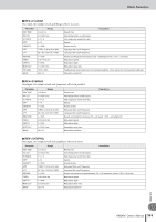
Effects Parameters ■ TREMOLO Two input, two output tremolo effect. Parameter FREQ. DEPTH WAVE LSH F LSH G EQ F EQ G EQ Q HSH F HSH G Range 0.05-40.00 Hz 0-100% Sine, Tri, Square 21.2 Hz-8.00 kHz -12.0 to +12.0 dB 100 Hz-8.00 kHz -12.0 to +12.0 dB 10.0-0.10 50.0 Hz-16.0 kHz -12.0 to +12.0 dB Modulation speed Modulation depth Modulation waveform Low shelving filter frequency Low shelving filter gain EQ (peaking type) frequency EQ (peaking type) gain EQ (peaking type) bandwidth High shelving filter frequency High shelving filter gain Description ■ HQ. PITCH One input, two output high-quality pitch shifter (Available for internal effects 1 and 2.). Parameter PITCH FINE DELAY FB. GAIN MODE Range -12 to +12 semitones -50 to +50 cents 0.0-1000.0 ms -99 to +99% 1-10 Description Pitch shift Pitch shift fine Delay time Feedback gain (plus values for normal-phase feedback, minus values for reverse-phase feedback) Pitch shift precision ■ DUAL PITCH Two input, two output pitch shifter. Parameter PITCH 1 FINE 1 LEVEL 1 PAN 1 DELAY 1 Range -24 to +24 semitones -50 to +50 cents -100 to +100% L63 to R63 0.0-1000.0 ms FB. G 1 -99 to +99% PITCH 2 FINE 2 LEVEL 2 PAN 2 DELAY 2 -24 to +24 semitones -50 to +50 cents -100 to +100% L63 to R63 0.0-1000.0 ms FB. G 2 -99 to +99% MODE 1-10 Description Channel #1 pitch shift Channel #1 pitch shift fine Channel #1 level (plus values for normal phase, minus values for reverse phase) Channel #1 pan Channel #1 delay time Channel #1 feedback gain (plus values for normal-phase feedback, minus values for reverse-phase feedback) Channel #2 pitch shift Channel #2 pitch shift fine Channel #2 level (plus values for normal phase, minus values for reverse phase) Channel #2 pan Channel #2 delay time Channel #2 feedback gain (plus values for normal-phase feedback, minus values for reverse-phase feedback) Pitch shift precision ■ ROTARY One input, two output rotary speaker simulator. Parameter ROTATE SPEED SLOW FAST DRIVE ACCEL LOW HIGH Range STOP, START SLOW, FAST 0.05-10.00 Hz 0.05-10.00 Hz 0-100 0-10 0-100 0-100 Description Rotation stop, start Rotation speed (see SLOW and FAST parameters) SLOW rotation speed FAST rotation speed Overdrive level Acceleration at speed changes Low-frequency filter High-frequency filter Appendix AW2400 Owner's Manual 249
-
 1
1 -
2
-
3
-
4
-
5
-
6
-
7
-
8
-
9
-
10
-
11
-
12
-
13
-
14
-
15
-
16
-
17
-
18
-
19
-
20
-
21
-
22
-
23
-
24
-
25
-
26
-
27
-
28
-
29
-
30
-
31
-
32
-
33
-
34
-
35
-
36
-
37
-
38
-
39
-
40
-
41
-
42
-
43
-
44
-
45
-
46
-
47
-
48
-
49
-
50
-
51
-
52
-
53
-
54
-
55
-
56
-
57
-
58
-
59
-
60
-
61
-
62
-
63
-
64
-
65
-
66
-
67
-
68
-
69
-
70
-
71
-
72
-
73
-
74
-
75
-
76
-
77
-
78
-
79
-
80
-
81
-
82
-
83
-
84
-
85
-
86
-
87
-
88
-
89
-
90
-
91
-
92
-
93
-
94
-
95
-
96
-
97
-
98
-
99
-
100
-
101
-
102
-
103
-
104
-
105
-
106
-
107
-
108
-
109
-
110
-
111
-
112
-
113
-
114
-
115
-
116
-
117
-
118
-
119
-
120
-
121
-
122
-
123
-
124
-
125
-
126
-
127
-
128
-
129
-
130
-
131
-
132
-
133
-
134
-
135
-
136
-
137
-
138
-
139
-
140
-
141
-
142
-
143
-
144
-
145
-
146
-
147
-
148
-
149
-
150
-
151
-
152
-
153
-
154
-
155
-
156
-
157
-
158
-
159
-
160
-
161
-
162
-
163
-
164
-
165
-
166
-
167
-
168
-
169
-
170
-
171
-
172
-
173
-
174
-
175
-
176
-
177
-
178
-
179
-
180
-
181
-
182
-
183
-
184
-
185
-
186
-
187
-
188
-
189
-
190
-
191
-
192
-
193
-
194
-
195
-
196
-
197
-
198
-
199
-
200
-
201
-
202
-
203
-
204
-
205
-
206
-
207
-
208
-
209
-
210
-
211
-
212
-
213
-
214
-
215
-
216
-
217
-
218
-
219
-
220
-
221
-
222
-
223
-
224
-
225
-
226
-
227
-
228
-
229
-
230
-
231
-
232
-
233
-
234
-
235
-
236
-
237
-
238
-
239
-
240
-
241
-
242
-
243
-
 244
244 -
 245
245 -
 246
246 -
 247
247 -
 248
248 -
 249
249 -
 250
250 -
 251
251 -
 252
252 -
 253
253 -
 254
254 -
255
-
256
-
257
-
258
-
259
-
260
-
261
-
262
-
263
-
264
-
265
-
266
-
267
-
268
-
269
-
270
-
271
-
272
-
273
-
274
-
275
-
276
-
277
-
278
-
279
-
280
-
281
-
282
-
283
-
284
-
285
-
286
-
287
-
288
 |
 |
