Yamaha AW2400 Owner's Manual - Page 18
Mixer Locate points/markers, Channels, Mixing Layers
 |
View all Yamaha AW2400 manuals
Add to My Manuals
Save this manual to your list of manuals |
Page 18 highlights
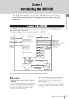
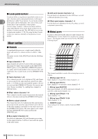
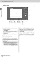
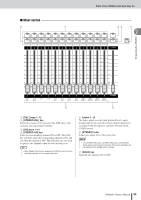
AW2400 terminology Introducing the AW2400 ■ Locate points/markers Locations within a song that you specified in order to execute a function such as auto punch-in/out or A-B repeat 2 playback are called "locate points." Locate points include in/out points and the A/B points. You can use the Locate section keys to move instantly to these points. You can assign "markers" at desired locations within a song independently of the locate points so that you can find these locations quickly. The AW2400 lets you set up to ninety-nine markers (1-99). By using the keys Locate section you can move instantly to the previous or next marker. Mixer section ■ Channels A signal path that processes a single signal within the mixer and sends it to various sections is called a "channel." The mixer section of the AW2400 provides the following channels. ● Input channels 1-16 Input channels provide level control, EQ, and dynamics processing for signals that are input via the [MIC/LINE INPUT] jacks 1-8, the [DIGITAL STEREO IN] connector, and/or an I/O card installed in the rear-panel slot, and send them to the recorder tracks or to the [STEREO OUT] jacks. ● Track channels 1-24 These channels provide level adjustment, EQ, and dynamics processing for the audio playback signals from audio tracks 1-24 of the recorder, and send the signals to the stereo track and the [STEREO OUT] jacks. You can also perform "bounce recording" by sending these channels to different tracks. ● Effect return channels 1-4 These channels send the signals returned from the internal effects to the stereo track and the [STEREO OUT] jacks. ● Stereo output channel This channel provides level adjustment, EQ, and dynamics processing for the stereo bus signal (which carries the mix of the other channels), and sends it to the stereo track or to the [STEREO OUT] jacks. The same signal is also output from the [MONITOR OUT] jacks and from the [PHONES] jack. ● Bus master channels 1/2 Provide level adjustment, EQ, and dynamics processing for the signals from bus 1 and bus 2, and sends the signals to the audio tracks. ● AUX send master channels 1-4 Provide final level adjustment for the AUX buses, as well as EQ and dynamics processing. ● Effect send master channels 1-4 Provide final level adjustment for the effect buses, as well as dynamics processing. ■ Mixing Layers In order to efficiently handle numerous input channels the AW2400 mixer section channels are organized in "mixing layers". The diagram shows an overview of the AW2400's 6 mixing layers. A B C D E F The channels available in each of the mixing layers are as follows. 1 Mixing Layer IN 1-8 Input channels 1-8 and effect return channels 1-4. B Mixing Layer IN 9-16 Input channels 9-16 and effect return channels 1-4. C Mixing Layer MASTER Bus master channels 1/2, AUX send master channels 1-4, and effect send master channels 1-4. D Mixing Layer TRACK 1-12 Track channels 1-12. E Mixing Layer TRACK 13-24 Track channels 13-24. F REMOTE Layer A special layer for remote control of external MIDI devices. 18 AW2400 Owner's Manual
-
 1
1 -
2
-
3
-
4
-
5
-
6
-
7
-
8
-
9
-
10
-
11
-
12
-
 13
13 -
 14
14 -
 15
15 -
 16
16 -
 17
17 -
 18
18 -
 19
19 -
 20
20 -
 21
21 -
 22
22 -
 23
23 -
24
-
25
-
26
-
27
-
28
-
29
-
30
-
31
-
32
-
33
-
34
-
35
-
36
-
37
-
38
-
39
-
40
-
41
-
42
-
43
-
44
-
45
-
46
-
47
-
48
-
49
-
50
-
51
-
52
-
53
-
54
-
55
-
56
-
57
-
58
-
59
-
60
-
61
-
62
-
63
-
64
-
65
-
66
-
67
-
68
-
69
-
70
-
71
-
72
-
73
-
74
-
75
-
76
-
77
-
78
-
79
-
80
-
81
-
82
-
83
-
84
-
85
-
86
-
87
-
88
-
89
-
90
-
91
-
92
-
93
-
94
-
95
-
96
-
97
-
98
-
99
-
100
-
101
-
102
-
103
-
104
-
105
-
106
-
107
-
108
-
109
-
110
-
111
-
112
-
113
-
114
-
115
-
116
-
117
-
118
-
119
-
120
-
121
-
122
-
123
-
124
-
125
-
126
-
127
-
128
-
129
-
130
-
131
-
132
-
133
-
134
-
135
-
136
-
137
-
138
-
139
-
140
-
141
-
142
-
143
-
144
-
145
-
146
-
147
-
148
-
149
-
150
-
151
-
152
-
153
-
154
-
155
-
156
-
157
-
158
-
159
-
160
-
161
-
162
-
163
-
164
-
165
-
166
-
167
-
168
-
169
-
170
-
171
-
172
-
173
-
174
-
175
-
176
-
177
-
178
-
179
-
180
-
181
-
182
-
183
-
184
-
185
-
186
-
187
-
188
-
189
-
190
-
191
-
192
-
193
-
194
-
195
-
196
-
197
-
198
-
199
-
200
-
201
-
202
-
203
-
204
-
205
-
206
-
207
-
208
-
209
-
210
-
211
-
212
-
213
-
214
-
215
-
216
-
217
-
218
-
219
-
220
-
221
-
222
-
223
-
224
-
225
-
226
-
227
-
228
-
229
-
230
-
231
-
232
-
233
-
234
-
235
-
236
-
237
-
238
-
239
-
240
-
241
-
242
-
243
-
244
-
245
-
246
-
247
-
248
-
249
-
250
-
251
-
252
-
253
-
254
-
255
-
256
-
257
-
258
-
259
-
260
-
261
-
262
-
263
-
264
-
265
-
266
-
267
-
268
-
269
-
270
-
271
-
272
-
273
-
274
-
275
-
276
-
277
-
278
-
279
-
280
-
281
-
282
-
283
-
284
-
285
-
286
-
287
-
288
 |
 |