Netgear M5300-52G3 Web Management User Guide - Page 185
Src/Dest MAC, VLAN, EType, incoming port, Src MAC
 |
View all Netgear M5300-52G3 manuals
Add to My Manuals
Save this manual to your list of manuals |
Page 185 highlights
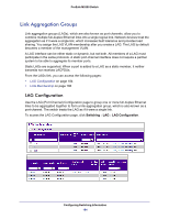
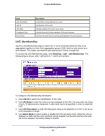
ProSafe M5300 Switch To configure LAG settings: 1. Use LAG Name to enter the name you want assigned to the LAG. You may enter any string of up to 15 alphanumeric characters. A valid name has to be specified in order to create the LAG. 2. Use Hash Mode to select the load-balancing mode used on a port-channel (LAG). Traffic is balanced on a port-channel (LAG) by selecting one of the links in the channel over which to transmit specific packets. The link is selected by creating a binary pattern from selected fields in a packet, and associating that pattern with a particular link: • Src MAC,VLAN,EType,incoming port - Source MAC, VLAN, EtherType, and incoming port associated with the packet. • Dest MAC,VLAN,EType,incoming port -Destination MAC, VLAN, EtherType, and incoming port associated with the packet. • Src/Dest MAC,VLAN,EType,incoming port - Source/Destination MAC, VLAN, EtherType, and incoming port associated with the packet. • Src IP and Src TCP/UDP Port fields - Source IP and Source TCP/UDP fields of the packet. • Dest IP and Dest TCP/UDP Port fields - Destination IP and Destination TCP/UDP Port fields of the packet. • Src/Dest IP and TCP/UDP Port Fields - Source/Destination IP and source/destination TCP/UDP Port fields of the packet. • Enhanced hashing mode - Features MODULO-N operation based on the number of ports in the LAG, non-Unicast traffic and unicast traffic hashing using a common hash algorithm, excellent load balancing performance, and packet attributes selection based on the packet type: • For L2 packets, source and destination MAC address are used for hash computation. • For L3 packets, source IP, destination IP address, TCP/UDP ports are used. 3. Use Link Trap to specify whether you want to have a trap sent when link status changes. The factory default is enable, which will cause the trap to be sent. 4. Use Admin Mode to select enable or disable from the pull-down menu. When the LAG is disabled no traffic will flow and LACPDUs will be dropped, but the links that form the LAG will not be released. The factory default is enable. 5. Use STP Mode to enable or disable the Spanning Tree Protocol Administrative Mode associated with the LAG. The possible values are: • Disable - Spanning tree is disabled for this LAG. • Enable - Spanning tree is enabled for this LAG. 6. Use Static Mode to select enable or disable from the pull-down menu. When the LAG is enabled it does not transmit or process received LACPDUs i.e. the member ports do not transmit LACPDUs and all the LACPDUs it may receive are dropped. The factory default is disable. 7. Click APPLY to update the switch with the changes. 8. Click DELETE to remove the currently selected configured LAG. All ports that were members of this LAG are removed from the LAG and included in the default VLAN. Configuring Switching Information 185
-
 1
1 -
2
-
3
-
4
-
5
-
6
-
7
-
8
-
9
-
10
-
11
-
12
-
13
-
14
-
15
-
16
-
17
-
18
-
19
-
20
-
21
-
22
-
23
-
24
-
25
-
26
-
27
-
28
-
29
-
30
-
31
-
32
-
33
-
34
-
35
-
36
-
37
-
38
-
39
-
40
-
41
-
42
-
43
-
44
-
45
-
46
-
47
-
48
-
49
-
50
-
51
-
52
-
53
-
54
-
55
-
56
-
57
-
58
-
59
-
60
-
61
-
62
-
63
-
64
-
65
-
66
-
67
-
68
-
69
-
70
-
71
-
72
-
73
-
74
-
75
-
76
-
77
-
78
-
79
-
80
-
81
-
82
-
83
-
84
-
85
-
86
-
87
-
88
-
89
-
90
-
91
-
92
-
93
-
94
-
95
-
96
-
97
-
98
-
99
-
100
-
101
-
102
-
103
-
104
-
105
-
106
-
107
-
108
-
109
-
110
-
111
-
112
-
113
-
114
-
115
-
116
-
117
-
118
-
119
-
120
-
121
-
122
-
123
-
124
-
125
-
126
-
127
-
128
-
129
-
130
-
131
-
132
-
133
-
134
-
135
-
136
-
137
-
138
-
139
-
140
-
141
-
142
-
143
-
144
-
145
-
146
-
147
-
148
-
149
-
150
-
151
-
152
-
153
-
154
-
155
-
156
-
157
-
158
-
159
-
160
-
161
-
162
-
163
-
164
-
165
-
166
-
167
-
168
-
169
-
170
-
171
-
172
-
173
-
174
-
175
-
176
-
177
-
178
-
179
-
 180
180 -
 181
181 -
 182
182 -
 183
183 -
 184
184 -
 185
185 -
 186
186 -
 187
187 -
 188
188 -
 189
189 -
 190
190 -
191
-
192
-
193
-
194
-
195
-
196
-
197
-
198
-
199
-
200
-
201
-
202
-
203
-
204
-
205
-
206
-
207
-
208
-
209
-
210
-
211
-
212
-
213
-
214
-
215
-
216
-
217
-
218
-
219
-
220
-
221
-
222
-
223
-
224
-
225
-
226
-
227
-
228
-
229
-
230
-
231
-
232
-
233
-
234
-
235
-
236
-
237
-
238
-
239
-
240
-
241
-
242
-
243
-
244
-
245
-
246
-
247
-
248
-
249
-
250
-
251
-
252
-
253
-
254
-
255
-
256
-
257
-
258
-
259
-
260
-
261
-
262
-
263
-
264
-
265
-
266
-
267
-
268
-
269
-
270
-
271
-
272
-
273
-
274
-
275
-
276
-
277
-
278
-
279
-
280
-
281
-
282
-
283
-
284
-
285
-
286
-
287
-
288
-
289
-
290
-
291
-
292
-
293
-
294
-
295
-
296
-
297
-
298
-
299
-
300
-
301
-
302
-
303
-
304
-
305
-
306
-
307
-
308
-
309
-
310
-
311
-
312
-
313
-
314
-
315
-
316
-
317
-
318
-
319
-
320
-
321
-
322
-
323
-
324
-
325
-
326
-
327
-
328
-
329
-
330
-
331
-
332
-
333
-
334
-
335
-
336
-
337
-
338
-
339
-
340
-
341
-
342
-
343
-
344
-
345
-
346
-
347
-
348
-
349
-
350
-
351
-
352
-
353
-
354
-
355
-
356
-
357
-
358
-
359
-
360
-
361
-
362
-
363
-
364
-
365
-
366
-
367
-
368
-
369
-
370
-
371
-
372
-
373
-
374
-
375
-
376
-
377
-
378
-
379
-
380
-
381
-
382
-
383
-
384
-
385
-
386
-
387
-
388
-
389
-
390
-
391
-
392
-
393
-
394
-
395
-
396
-
397
-
398
-
399
-
400
-
401
-
402
-
403
-
404
-
405
-
406
-
407
-
408
-
409
-
410
-
411
-
412
-
413
-
414
-
415
-
416
-
417
-
418
-
419
-
420
-
421
-
422
-
423
-
424
-
425
-
426
-
427
-
428
-
429
-
430
-
431
-
432
-
433
-
434
-
435
-
436
-
437
-
438
-
439
-
440
-
441
-
442
-
443
-
444
-
445
-
446
-
447
-
448
-
449
-
450
-
451
-
452
-
453
-
454
-
455
-
456
-
457
-
458
-
459
-
460
-
461
-
462
-
463
-
464
-
465
-
466
-
467
-
468
-
469
-
470
-
471
-
472
-
473
-
474
-
475
-
476
-
477
-
478
-
479
-
480
-
481
-
482
-
483
-
484
-
485
-
486
-
487
-
488
-
489
-
490
-
491
-
492
-
493
-
494
-
495
-
496
-
497
-
498
-
499
-
500
-
501
-
502
-
503
-
504
-
505
-
506
-
507
-
508
-
509
-
510
-
511
-
512
-
513
-
514
-
515
-
516
-
517
-
518
-
519
-
520
-
521
-
522
-
523
-
524
-
525
-
526
-
527
-
528
-
529
-
530
 |
 |