Brother International HL 1850 Service Manual - Page 118
Brother International HL 1850 - B/W Laser Printer Manual
 |
UPC - 012502603900
View all Brother International HL 1850 manuals
Add to My Manuals
Save this manual to your list of manuals |
Page 118 highlights
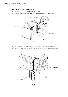
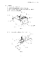
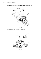
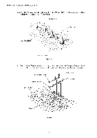
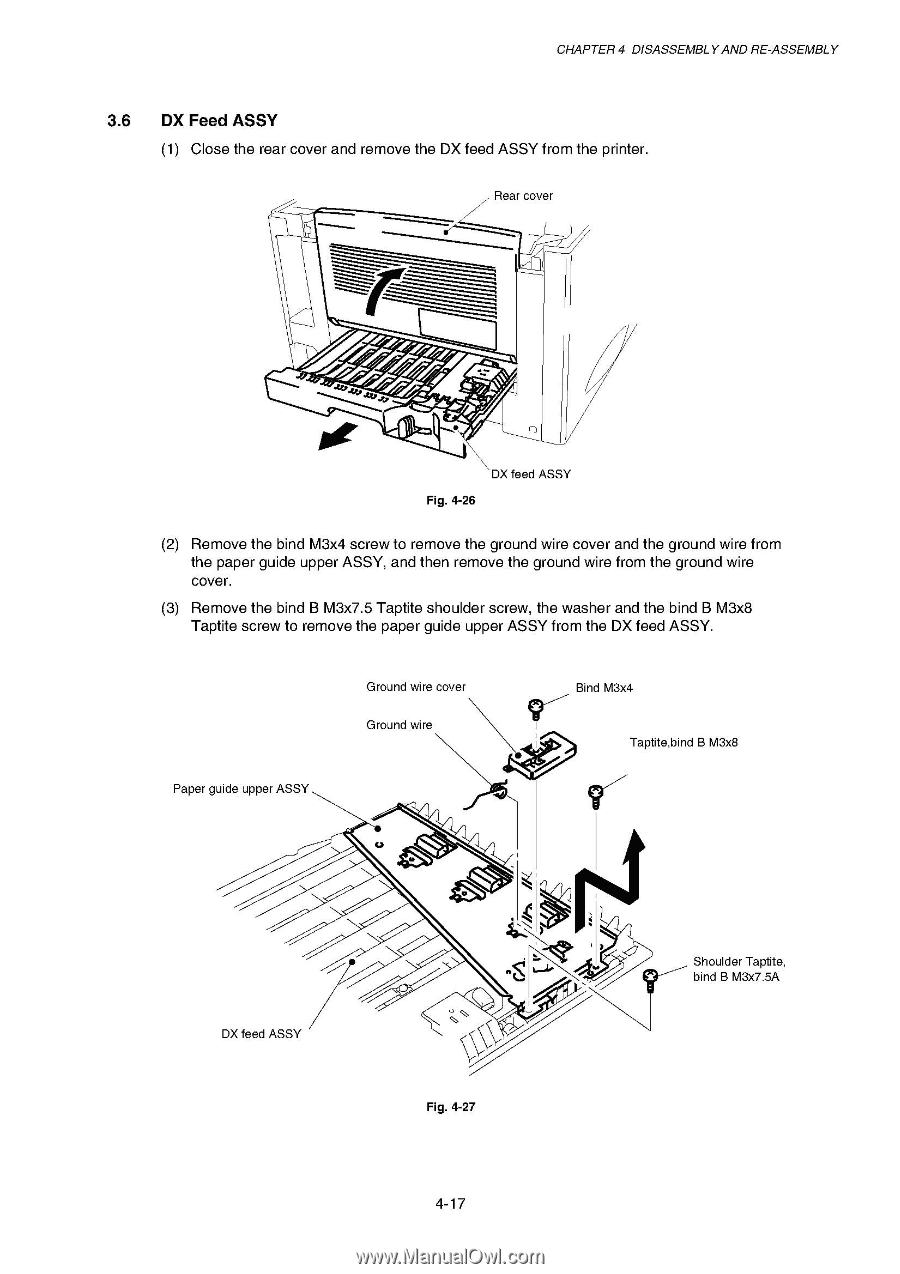
CHAPTER 4 DISASSEMBLY AND RE-ASSEMBLY 3.6 DX Feed ASSY (1) Close the rear cover and remove the DX feed ASSY from the printer. Rear cover el of DX feed ASSY Fig. 4-26 (2) Remove the bind M3x4 screw to remove the ground wire cover and the ground wire from the paper guide upper ASSY, and then remove the ground wire from the ground wire cover. (3) Remove the bind B M3x7.5 Taptite shoulder screw, the washer and the bind B M3x8 Taptite screw to remove the paper guide upper ASSY from the DX feed ASSY. Paper guide upper ASSY Ground wire cover Ground wire Bind M3x4 9' i Taptite,bind B M3x8 c., 4% DX feed ASSY Shoulder Taptite, bind B M3x7.5A Fig. 4-27 4-17
-
 1
1 -
2
-
3
-
4
-
5
-
6
-
7
-
8
-
9
-
10
-
11
-
12
-
13
-
14
-
15
-
16
-
17
-
18
-
19
-
20
-
21
-
22
-
23
-
24
-
25
-
26
-
27
-
28
-
29
-
30
-
31
-
32
-
33
-
34
-
35
-
36
-
37
-
38
-
39
-
40
-
41
-
42
-
43
-
44
-
45
-
46
-
47
-
48
-
49
-
50
-
51
-
52
-
53
-
54
-
55
-
56
-
57
-
58
-
59
-
60
-
61
-
62
-
63
-
64
-
65
-
66
-
67
-
68
-
69
-
70
-
71
-
72
-
73
-
74
-
75
-
76
-
77
-
78
-
79
-
80
-
81
-
82
-
83
-
84
-
85
-
86
-
87
-
88
-
89
-
90
-
91
-
92
-
93
-
94
-
95
-
96
-
97
-
98
-
99
-
100
-
101
-
102
-
103
-
104
-
105
-
106
-
107
-
108
-
109
-
110
-
111
-
112
-
 113
113 -
 114
114 -
 115
115 -
 116
116 -
 117
117 -
 118
118 -
 119
119 -
 120
120 -
 121
121 -
 122
122 -
 123
123 -
124
-
125
-
126
-
127
-
128
-
129
-
130
-
131
-
132
-
133
-
134
-
135
-
136
-
137
-
138
-
139
-
140
-
141
-
142
-
143
-
144
-
145
-
146
-
147
-
148
-
149
-
150
-
151
-
152
-
153
-
154
-
155
-
156
-
157
-
158
-
159
-
160
-
161
-
162
-
163
-
164
-
165
-
166
-
167
-
168
-
169
-
170
-
171
-
172
-
173
-
174
-
175
-
176
-
177
-
178
-
179
-
180
-
181
-
182
-
183
-
184
-
185
-
186
-
187
-
188
-
189
-
190
-
191
-
192
-
193
-
194
-
195
-
196
-
197
-
198
-
199
-
200
-
201
-
202
-
203
-
204
-
205
-
206
-
207
-
208
-
209
-
210
-
211
-
212
-
213
-
214
-
215
-
216
-
217
-
218
-
219
-
220
-
221
-
222
-
223
-
224
-
225
-
226
-
227
-
228
-
229
-
230
-
231
-
232
-
233
-
234
-
235
-
236
-
237
-
238
-
239
-
240
-
241
-
242
-
243
-
244
-
245
-
246
-
247
-
248
-
249
-
250
-
251
-
252
-
253
-
254
-
255
-
256
-
257
-
258
-
259
-
260
-
261
-
262
-
263
-
264
-
265
-
266
-
267
-
268
-
269
-
270
-
271
-
272
-
273
-
274
-
275
-
276
-
277
 |
 |
CHAPTER
4
DISASSEMBLY
AND
RE
-ASSEMBLY
3.6
DX
Feed
ASSY
(1)
Close
the
rear
cover
and
remove
the
DX
feed
ASSY
from
the
printer.
Rear
cover
............................
---
--,—..----
--
......
,
el •••
...of
DX
feed
ASSY
Fig.
4-26
(2)
Remove
the
bind
M3x4
screw
to
remove
the
ground
wire
cover
and
the
ground
wire
from
the
paper
guide
upper
ASSY,
and
then
remove
the
ground
wire
from
the
ground
wire
cover.
(3)
Remove
the
bind
B
M3x7.5
Taptite
shoulder
screw,
the
washer
and
the
bind
B
M3x8
Taptite
screw
to
remove
the
paper
guide
upper
ASSY
from
the
DX
feed
ASSY.
Ground
wire
cover
Bind
M3x4
Ground
wire
Paper
guide
upper
ASSY
c.,
DX
feed
ASSY
4
%
Fig.
4-27
9'
i
Taptite,bind
B
M3x8
Shoulder
Taptite,
bind
B
M3x7.5A
4-17