Brother International HL 1850 Service Manual - Page 233
Ctpedsmrfgl2
 |
UPC - 012502603900
View all Brother International HL 1850 manuals
Add to My Manuals
Save this manual to your list of manuals |
Page 233 highlights
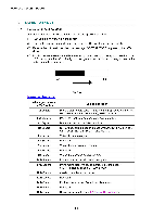
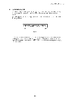
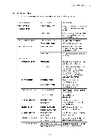
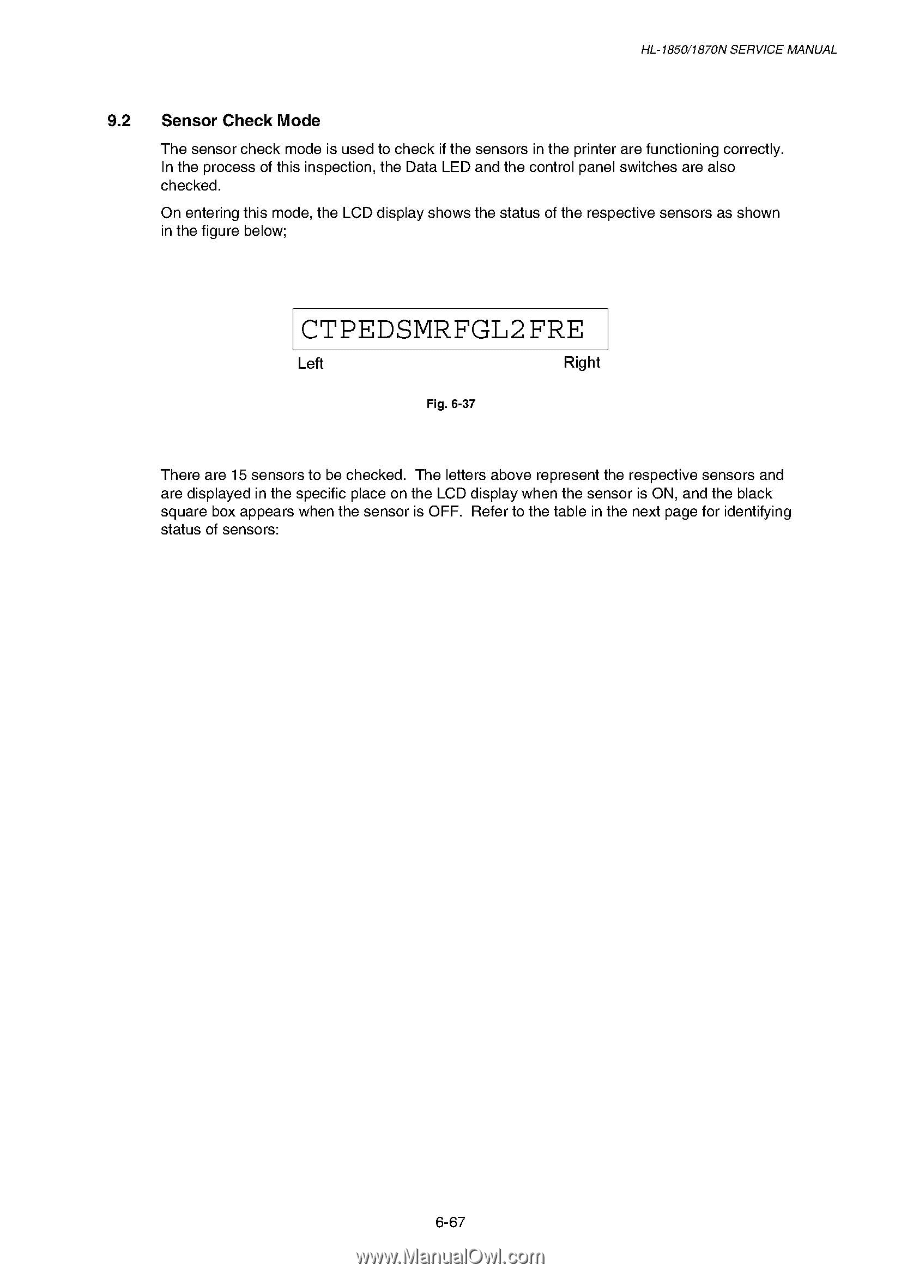
HL-1850/1870N SERVICE MANUAL 9.2 Sensor Check Mode The sensor check mode is used to check if the sensors in the printer are functioning correctly. In the process of this inspection, the Data LED and the control panel switches are also checked. On entering this mode, the LCD display shows the status of the respective sensors as shown in the figure below; CTPEDSMRFGL2 FRE Left Right Fig. 6-37 There are 15 sensors to be checked. The letters above represent the respective sensors and are displayed in the specific place on the LCD display when the sensor is ON, and the black square box appears when the sensor is OFF. Refer to the table in the next page for identifying status of sensors: 6-67
-
 1
1 -
2
-
3
-
4
-
5
-
6
-
7
-
8
-
9
-
10
-
11
-
12
-
13
-
14
-
15
-
16
-
17
-
18
-
19
-
20
-
21
-
22
-
23
-
24
-
25
-
26
-
27
-
28
-
29
-
30
-
31
-
32
-
33
-
34
-
35
-
36
-
37
-
38
-
39
-
40
-
41
-
42
-
43
-
44
-
45
-
46
-
47
-
48
-
49
-
50
-
51
-
52
-
53
-
54
-
55
-
56
-
57
-
58
-
59
-
60
-
61
-
62
-
63
-
64
-
65
-
66
-
67
-
68
-
69
-
70
-
71
-
72
-
73
-
74
-
75
-
76
-
77
-
78
-
79
-
80
-
81
-
82
-
83
-
84
-
85
-
86
-
87
-
88
-
89
-
90
-
91
-
92
-
93
-
94
-
95
-
96
-
97
-
98
-
99
-
100
-
101
-
102
-
103
-
104
-
105
-
106
-
107
-
108
-
109
-
110
-
111
-
112
-
113
-
114
-
115
-
116
-
117
-
118
-
119
-
120
-
121
-
122
-
123
-
124
-
125
-
126
-
127
-
128
-
129
-
130
-
131
-
132
-
133
-
134
-
135
-
136
-
137
-
138
-
139
-
140
-
141
-
142
-
143
-
144
-
145
-
146
-
147
-
148
-
149
-
150
-
151
-
152
-
153
-
154
-
155
-
156
-
157
-
158
-
159
-
160
-
161
-
162
-
163
-
164
-
165
-
166
-
167
-
168
-
169
-
170
-
171
-
172
-
173
-
174
-
175
-
176
-
177
-
178
-
179
-
180
-
181
-
182
-
183
-
184
-
185
-
186
-
187
-
188
-
189
-
190
-
191
-
192
-
193
-
194
-
195
-
196
-
197
-
198
-
199
-
200
-
201
-
202
-
203
-
204
-
205
-
206
-
207
-
208
-
209
-
210
-
211
-
212
-
213
-
214
-
215
-
216
-
217
-
218
-
219
-
220
-
221
-
222
-
223
-
224
-
225
-
226
-
227
-
 228
228 -
 229
229 -
 230
230 -
 231
231 -
 232
232 -
 233
233 -
 234
234 -
 235
235 -
 236
236 -
 237
237 -
 238
238 -
239
-
240
-
241
-
242
-
243
-
244
-
245
-
246
-
247
-
248
-
249
-
250
-
251
-
252
-
253
-
254
-
255
-
256
-
257
-
258
-
259
-
260
-
261
-
262
-
263
-
264
-
265
-
266
-
267
-
268
-
269
-
270
-
271
-
272
-
273
-
274
-
275
-
276
-
277
 |
 |
HL
-1850/1870N
SERVICE
MANUAL
9.2
Sensor
Check
Mode
The
sensor
check
mode
is
used
to
check
if
the
sensors
in
the
printer
are
functioning
correctly.
In
the
process
of
this
inspection,
the
Data
LED
and
the
control
panel
switches
are
also
checked.
On
entering
this
mode,
the
LCD
display
shows
the
status
of
the
respective
sensors
as
shown
in
the
figure
below;
CTPEDSMRFGL2
FRE
Left
Fig.
6-37
Right
There
are
15
sensors
to
be
checked.
The
letters
above
represent
the
respective
sensors
and
are
displayed
in
the
specific
place
on
the
LCD
display
when
the
sensor
is
ON,
and
the
black
square
box
appears
when
the
sensor
is
OFF.
Refer
to
the
table
in
the
next
page
for
identifying
status
of
sensors:
6-67