Brother International HL 1850 Service Manual - Page 146
Sc Ok
 |
UPC - 012502603900
View all Brother International HL 1850 manuals
Add to My Manuals
Save this manual to your list of manuals |
Page 146 highlights
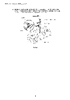
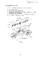
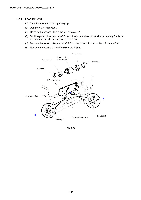
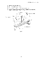
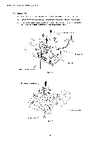
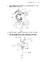
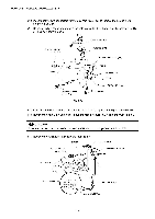
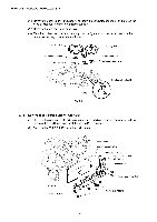
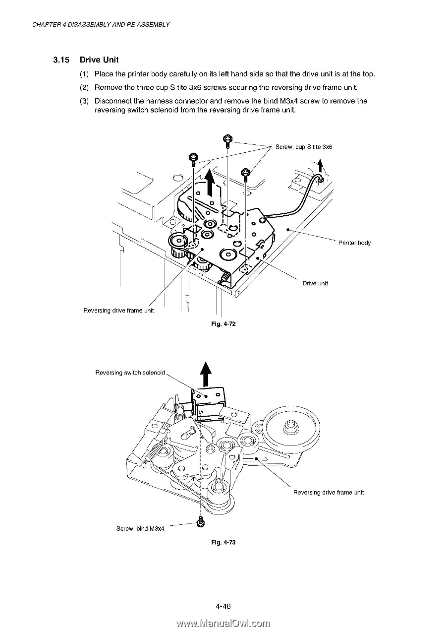
CHAPTER 4 DISASSEMBLY AND RE-ASSEMBLY 3.15 Drive Unit (1) Place the printer body carefully on its left hand side so that the drive unit is at the top. (2) Remove the three cup S tite 3x6 screws securing the reversing drive frame unit. (3) Disconnect the harness connector and remove the bind M3x4 screw to remove the reversing switch solenoid from the reversing drive frame unit. Screw, cup S tite 3x6 O ck :V ....• 0 0 0 Reversing drive frame unit Fig. 4-72 Printer body Drive unit Reversing switch solenoid .1% 0 / / c/? 0 ----_____ Screw, bind M3x4 Fig. 4-73 a Reversing drive frame unit 4-46
-
 1
1 -
2
-
3
-
4
-
5
-
6
-
7
-
8
-
9
-
10
-
11
-
12
-
13
-
14
-
15
-
16
-
17
-
18
-
19
-
20
-
21
-
22
-
23
-
24
-
25
-
26
-
27
-
28
-
29
-
30
-
31
-
32
-
33
-
34
-
35
-
36
-
37
-
38
-
39
-
40
-
41
-
42
-
43
-
44
-
45
-
46
-
47
-
48
-
49
-
50
-
51
-
52
-
53
-
54
-
55
-
56
-
57
-
58
-
59
-
60
-
61
-
62
-
63
-
64
-
65
-
66
-
67
-
68
-
69
-
70
-
71
-
72
-
73
-
74
-
75
-
76
-
77
-
78
-
79
-
80
-
81
-
82
-
83
-
84
-
85
-
86
-
87
-
88
-
89
-
90
-
91
-
92
-
93
-
94
-
95
-
96
-
97
-
98
-
99
-
100
-
101
-
102
-
103
-
104
-
105
-
106
-
107
-
108
-
109
-
110
-
111
-
112
-
113
-
114
-
115
-
116
-
117
-
118
-
119
-
120
-
121
-
122
-
123
-
124
-
125
-
126
-
127
-
128
-
129
-
130
-
131
-
132
-
133
-
134
-
135
-
136
-
137
-
138
-
139
-
140
-
 141
141 -
 142
142 -
 143
143 -
 144
144 -
 145
145 -
 146
146 -
 147
147 -
 148
148 -
 149
149 -
 150
150 -
 151
151 -
152
-
153
-
154
-
155
-
156
-
157
-
158
-
159
-
160
-
161
-
162
-
163
-
164
-
165
-
166
-
167
-
168
-
169
-
170
-
171
-
172
-
173
-
174
-
175
-
176
-
177
-
178
-
179
-
180
-
181
-
182
-
183
-
184
-
185
-
186
-
187
-
188
-
189
-
190
-
191
-
192
-
193
-
194
-
195
-
196
-
197
-
198
-
199
-
200
-
201
-
202
-
203
-
204
-
205
-
206
-
207
-
208
-
209
-
210
-
211
-
212
-
213
-
214
-
215
-
216
-
217
-
218
-
219
-
220
-
221
-
222
-
223
-
224
-
225
-
226
-
227
-
228
-
229
-
230
-
231
-
232
-
233
-
234
-
235
-
236
-
237
-
238
-
239
-
240
-
241
-
242
-
243
-
244
-
245
-
246
-
247
-
248
-
249
-
250
-
251
-
252
-
253
-
254
-
255
-
256
-
257
-
258
-
259
-
260
-
261
-
262
-
263
-
264
-
265
-
266
-
267
-
268
-
269
-
270
-
271
-
272
-
273
-
274
-
275
-
276
-
277
 |
 |
CHAPTER
4
DISASSEMBLY
AND
RE
-ASSEMBLY
3.15
Drive
Unit
(1)
Place
the
printer
body
carefully
on
its
left
hand
side
so
that
the
drive
unit
is
at
the
top.
(2)
Remove
the
three
cup
S
tite
3x6
screws
securing
the
reversing
drive
frame
unit.
(3)
Disconnect
the
harness
connector
and
remove
the
bind
M3x4
screw
to remove
the
reversing
switch
solenoid
from
the
reversing
drive
frame
unit.
Screw,
cup
S
tite
3x6
O
0
c
k
Reversing
drive
frame
unit
Reversing
switch
solenoid
0
/
0
----_____
Screw,
bind
M3x4
:
V
....
•
.1%
0
Fig.
4-72
/
c
/
?
Fig.
4-73
0
Drive
unit
a
Printer
body
Reversing
drive
frame
unit
4-46