Brother International HL 1850 Service Manual - Page 199
Scanner, failure, Fuser
 |
UPC - 012502603900
View all Brother International HL 1850 manuals
Add to My Manuals
Save this manual to your list of manuals |
Page 199 highlights
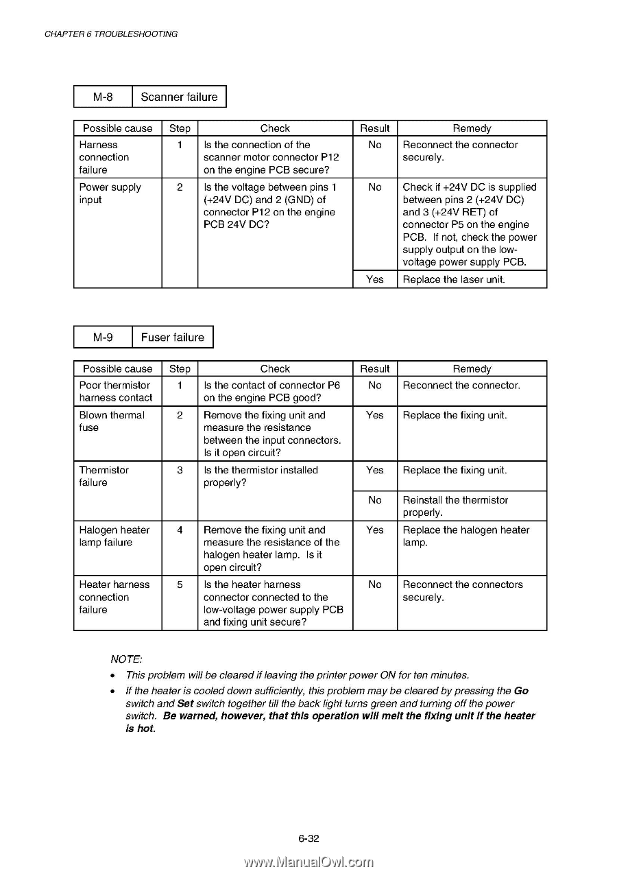
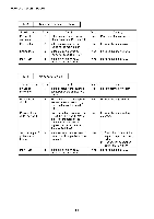
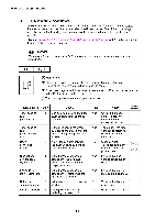
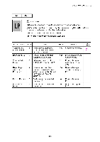
CHAPTER 6 TROUBLESHOOTING M-8 Scanner failure Possible cause Harness connection failure Power supply input Step 1 2 Check Is the connection of the scanner motor connector P12 on the engine PCB secure? Is the voltage between pins 1 (+24V DC) and 2 (GND) of connector P12 on the engine PCB 24V DC? Result No Remedy Reconnect the connector securely. No Check if +24V DC is supplied between pins 2 (+24V DC) and 3 (+24V RET) of connector P5 on the engine PCB. If not, check the power supply output on the lowvoltage power supply PCB. Yes Replace the laser unit. M-9 Fuser failure Possible cause Poor thermistor harness contact Blown thermal fuse Thermistor failure Halogen heater lamp failure Heater harness connection failure Step 1 2 3 Check Is the contact of connector P6 on the engine PCB good? Remove the fixing unit and measure the resistance between the input connectors. Is it open circuit? Is the thermistor installed properly? 4 Remove the fixing unit and measure the resistance of the halogen heater lamp. Is it open circuit? 5 Is the heater harness connector connected to the low-voltage power supply PCB and fixing unit secure? Result Remedy No Reconnect the connector. Yes Replace the fixing unit. Yes Replace the fixing unit. No Reinstall the thermistor properly. Yes Replace the halogen heater lamp. No Reconnect the connectors securely. NOTE: • This problem will be clearedifleaving the printerpower ON for ten minutes. • If the heater is cooled down sufficiently, this problem may be cleared by pressing the Go switch and Set switch together till the back light turns green and turning off the power switch. Be warned, however, that this operation will melt the fixing unit if the heater is hot. 6-32
-
 1
1 -
2
-
3
-
4
-
5
-
6
-
7
-
8
-
9
-
10
-
11
-
12
-
13
-
14
-
15
-
16
-
17
-
18
-
19
-
20
-
21
-
22
-
23
-
24
-
25
-
26
-
27
-
28
-
29
-
30
-
31
-
32
-
33
-
34
-
35
-
36
-
37
-
38
-
39
-
40
-
41
-
42
-
43
-
44
-
45
-
46
-
47
-
48
-
49
-
50
-
51
-
52
-
53
-
54
-
55
-
56
-
57
-
58
-
59
-
60
-
61
-
62
-
63
-
64
-
65
-
66
-
67
-
68
-
69
-
70
-
71
-
72
-
73
-
74
-
75
-
76
-
77
-
78
-
79
-
80
-
81
-
82
-
83
-
84
-
85
-
86
-
87
-
88
-
89
-
90
-
91
-
92
-
93
-
94
-
95
-
96
-
97
-
98
-
99
-
100
-
101
-
102
-
103
-
104
-
105
-
106
-
107
-
108
-
109
-
110
-
111
-
112
-
113
-
114
-
115
-
116
-
117
-
118
-
119
-
120
-
121
-
122
-
123
-
124
-
125
-
126
-
127
-
128
-
129
-
130
-
131
-
132
-
133
-
134
-
135
-
136
-
137
-
138
-
139
-
140
-
141
-
142
-
143
-
144
-
145
-
146
-
147
-
148
-
149
-
150
-
151
-
152
-
153
-
154
-
155
-
156
-
157
-
158
-
159
-
160
-
161
-
162
-
163
-
164
-
165
-
166
-
167
-
168
-
169
-
170
-
171
-
172
-
173
-
174
-
175
-
176
-
177
-
178
-
179
-
180
-
181
-
182
-
183
-
184
-
185
-
186
-
187
-
188
-
189
-
190
-
191
-
192
-
193
-
 194
194 -
 195
195 -
 196
196 -
 197
197 -
 198
198 -
 199
199 -
 200
200 -
 201
201 -
 202
202 -
 203
203 -
 204
204 -
205
-
206
-
207
-
208
-
209
-
210
-
211
-
212
-
213
-
214
-
215
-
216
-
217
-
218
-
219
-
220
-
221
-
222
-
223
-
224
-
225
-
226
-
227
-
228
-
229
-
230
-
231
-
232
-
233
-
234
-
235
-
236
-
237
-
238
-
239
-
240
-
241
-
242
-
243
-
244
-
245
-
246
-
247
-
248
-
249
-
250
-
251
-
252
-
253
-
254
-
255
-
256
-
257
-
258
-
259
-
260
-
261
-
262
-
263
-
264
-
265
-
266
-
267
-
268
-
269
-
270
-
271
-
272
-
273
-
274
-
275
-
276
-
277
 |
 |