Brother International HL 1850 Service Manual - Page 138
M3x12
 |
UPC - 012502603900
View all Brother International HL 1850 manuals
Add to My Manuals
Save this manual to your list of manuals |
Page 138 highlights
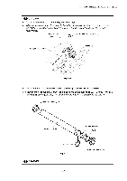
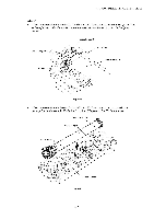
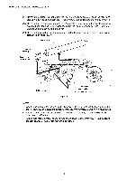
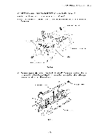
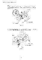
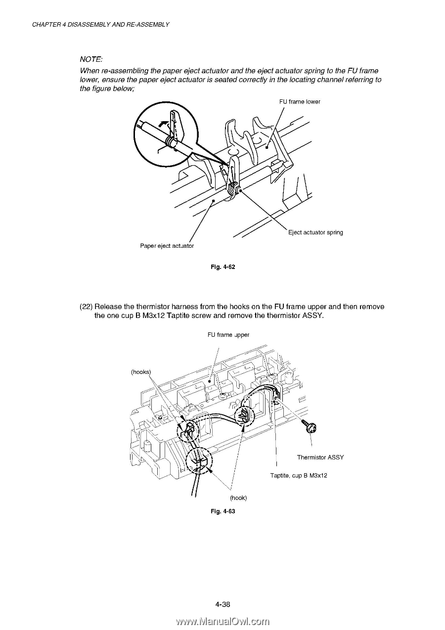
CHAPTER 4 DISASSEMBLY AND RE-ASSEMBLY NOTE: When re-assembling the paper eject actuator and the eject actuator spring to the FU frame lower, ensure the paper eject actuator is seated correctly in the locating channel referring to the figure below; FU frame lower 1 er t t Paper eject actuator Fig. 4-62 Eject actuator spring (22) Release the thermistor harness from the hooks on the FU frame upper and then remove the one cup B M3x12 Taptite screw and remove the thermistor ASSY. FU frame upper (hooks) I , , N C.) ,-, N . --- % .., t t t (hook) Fig. 4-63 Thermistor ASSY Taptite, cup B M3x12 4-38
-
 1
1 -
2
-
3
-
4
-
5
-
6
-
7
-
8
-
9
-
10
-
11
-
12
-
13
-
14
-
15
-
16
-
17
-
18
-
19
-
20
-
21
-
22
-
23
-
24
-
25
-
26
-
27
-
28
-
29
-
30
-
31
-
32
-
33
-
34
-
35
-
36
-
37
-
38
-
39
-
40
-
41
-
42
-
43
-
44
-
45
-
46
-
47
-
48
-
49
-
50
-
51
-
52
-
53
-
54
-
55
-
56
-
57
-
58
-
59
-
60
-
61
-
62
-
63
-
64
-
65
-
66
-
67
-
68
-
69
-
70
-
71
-
72
-
73
-
74
-
75
-
76
-
77
-
78
-
79
-
80
-
81
-
82
-
83
-
84
-
85
-
86
-
87
-
88
-
89
-
90
-
91
-
92
-
93
-
94
-
95
-
96
-
97
-
98
-
99
-
100
-
101
-
102
-
103
-
104
-
105
-
106
-
107
-
108
-
109
-
110
-
111
-
112
-
113
-
114
-
115
-
116
-
117
-
118
-
119
-
120
-
121
-
122
-
123
-
124
-
125
-
126
-
127
-
128
-
129
-
130
-
131
-
132
-
 133
133 -
 134
134 -
 135
135 -
 136
136 -
 137
137 -
 138
138 -
 139
139 -
 140
140 -
 141
141 -
 142
142 -
 143
143 -
144
-
145
-
146
-
147
-
148
-
149
-
150
-
151
-
152
-
153
-
154
-
155
-
156
-
157
-
158
-
159
-
160
-
161
-
162
-
163
-
164
-
165
-
166
-
167
-
168
-
169
-
170
-
171
-
172
-
173
-
174
-
175
-
176
-
177
-
178
-
179
-
180
-
181
-
182
-
183
-
184
-
185
-
186
-
187
-
188
-
189
-
190
-
191
-
192
-
193
-
194
-
195
-
196
-
197
-
198
-
199
-
200
-
201
-
202
-
203
-
204
-
205
-
206
-
207
-
208
-
209
-
210
-
211
-
212
-
213
-
214
-
215
-
216
-
217
-
218
-
219
-
220
-
221
-
222
-
223
-
224
-
225
-
226
-
227
-
228
-
229
-
230
-
231
-
232
-
233
-
234
-
235
-
236
-
237
-
238
-
239
-
240
-
241
-
242
-
243
-
244
-
245
-
246
-
247
-
248
-
249
-
250
-
251
-
252
-
253
-
254
-
255
-
256
-
257
-
258
-
259
-
260
-
261
-
262
-
263
-
264
-
265
-
266
-
267
-
268
-
269
-
270
-
271
-
272
-
273
-
274
-
275
-
276
-
277
 |
 |
CHAPTER
4
DISASSEMBLY
AND
RE
-ASSEMBLY
NOTE:
When
re
-assembling
the
paper
eject
actuator
and
the
eject
actuator
spring
to
the
FU
frame
lower,
ensure
the
paper
eject
actuator
is
seated
correctly
in
the
locating
channel
referring
to
the
figure
below;
FU
frame
lower
1
e
r
t
t
Eject
actuator
spring
Paper
eject
actuator
Fig.
4-62
(22)
Release
the
thermistor
harness
from
the
hooks
on
the
FU
frame
upper
and
then
remove
the
one
cup
B
M3x12
Taptite
screw
and
remove
the
thermistor
ASSY.
FU
frame
upper
(hooks)
N
I
%
.
,
C.)
,-,
t
t
t
..,
(hook)
Fig.
4-63
,
N
---
Thermistor
ASSY
Taptite,
cup
B
M3x12
4-38