Brother International HL 1850 Service Manual - Page 150
to remove
 |
UPC - 012502603900
View all Brother International HL 1850 manuals
Add to My Manuals
Save this manual to your list of manuals |
Page 150 highlights
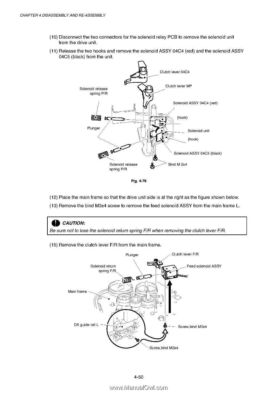
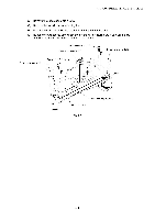
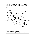
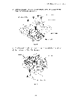
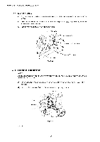
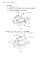
CHAPTER 4 DISASSEMBLY AND RE-ASSEMBLY (10) Disconnect the two connectors for the solenoid relay PCB to remove the solenoid unit from the drive unit. (11) Release the two hooks and remove the solenoid ASSY 04C4 (red) and the solenoid ASSY 04C5 (black) from the unit. Clutch lever 04C4 Solenoid release spring P/R Clutch lever MP 0 Solenoid ASSY 04C4 (red) Plunger -) (hook) ! Solenoid unit ti (hook) oNA Solenoid release spring P/R Solenoid ASSY 04C5 (black) Bind M 2x4 Fig. 4-79 (12) Place the main frame so that the drive unit side is at the right as the figure shown below. (13) Remove the bind M3x4 screw to remove the feed solenoid ASSY from the main frame L. CAUTION: Be sure not to lose the solenoid return spring FIR when removing the clutch lever FIR. (15) Remove the clutch lever F/R from the main frame. Plunger Solenoid return spring F/R Clutch lever F/R Feed solenoid ASSY Main frame 0 DX guide rail L N 8 Screw,bind M3x4 Screw,bind M3x4 4-50
-
 1
1 -
2
-
3
-
4
-
5
-
6
-
7
-
8
-
9
-
10
-
11
-
12
-
13
-
14
-
15
-
16
-
17
-
18
-
19
-
20
-
21
-
22
-
23
-
24
-
25
-
26
-
27
-
28
-
29
-
30
-
31
-
32
-
33
-
34
-
35
-
36
-
37
-
38
-
39
-
40
-
41
-
42
-
43
-
44
-
45
-
46
-
47
-
48
-
49
-
50
-
51
-
52
-
53
-
54
-
55
-
56
-
57
-
58
-
59
-
60
-
61
-
62
-
63
-
64
-
65
-
66
-
67
-
68
-
69
-
70
-
71
-
72
-
73
-
74
-
75
-
76
-
77
-
78
-
79
-
80
-
81
-
82
-
83
-
84
-
85
-
86
-
87
-
88
-
89
-
90
-
91
-
92
-
93
-
94
-
95
-
96
-
97
-
98
-
99
-
100
-
101
-
102
-
103
-
104
-
105
-
106
-
107
-
108
-
109
-
110
-
111
-
112
-
113
-
114
-
115
-
116
-
117
-
118
-
119
-
120
-
121
-
122
-
123
-
124
-
125
-
126
-
127
-
128
-
129
-
130
-
131
-
132
-
133
-
134
-
135
-
136
-
137
-
138
-
139
-
140
-
141
-
142
-
143
-
144
-
 145
145 -
 146
146 -
 147
147 -
 148
148 -
 149
149 -
 150
150 -
 151
151 -
 152
152 -
 153
153 -
 154
154 -
 155
155 -
156
-
157
-
158
-
159
-
160
-
161
-
162
-
163
-
164
-
165
-
166
-
167
-
168
-
169
-
170
-
171
-
172
-
173
-
174
-
175
-
176
-
177
-
178
-
179
-
180
-
181
-
182
-
183
-
184
-
185
-
186
-
187
-
188
-
189
-
190
-
191
-
192
-
193
-
194
-
195
-
196
-
197
-
198
-
199
-
200
-
201
-
202
-
203
-
204
-
205
-
206
-
207
-
208
-
209
-
210
-
211
-
212
-
213
-
214
-
215
-
216
-
217
-
218
-
219
-
220
-
221
-
222
-
223
-
224
-
225
-
226
-
227
-
228
-
229
-
230
-
231
-
232
-
233
-
234
-
235
-
236
-
237
-
238
-
239
-
240
-
241
-
242
-
243
-
244
-
245
-
246
-
247
-
248
-
249
-
250
-
251
-
252
-
253
-
254
-
255
-
256
-
257
-
258
-
259
-
260
-
261
-
262
-
263
-
264
-
265
-
266
-
267
-
268
-
269
-
270
-
271
-
272
-
273
-
274
-
275
-
276
-
277
 |
 |