Brother International HL 1850 Service Manual - Page 135
DISASSEMBLY, ASSEMBLY, roller, projection, bearing, fingers, frame, upper
 |
UPC - 012502603900
View all Brother International HL 1850 manuals
Add to My Manuals
Save this manual to your list of manuals |
Page 135 highlights
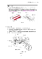
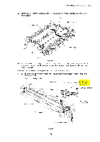
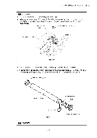
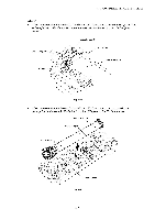
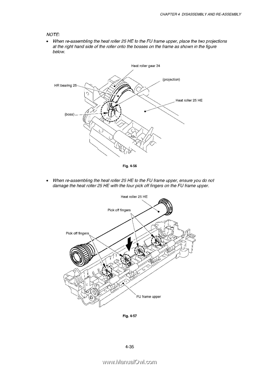
CHAPTER 4 DISASSEMBLY AND RE-ASSEMBLY NOTE: • When re-assembling the heat roller 25 HE to the FU frame upper, place the two projections at the right hand side of the roller onto the bosses on the frame as shown in the figure below. Heat roller gear 34 HR bearing 25 projection) (boSS) 7 4 , I I .\ i Heat roller 25 HE Fig. 4-56 • When re-assembling the heat roller 25 HE to the FU frame upper, ensure you do not damage the heat roller 25 HE with the four pick off fingers on the FU frame upper. Heat roller 25 HE Pick off fingers Pick off fingers N -f v % !I 1 f 1, i / V FU frame upper Fig. 4-57
-
 1
1 -
2
-
3
-
4
-
5
-
6
-
7
-
8
-
9
-
10
-
11
-
12
-
13
-
14
-
15
-
16
-
17
-
18
-
19
-
20
-
21
-
22
-
23
-
24
-
25
-
26
-
27
-
28
-
29
-
30
-
31
-
32
-
33
-
34
-
35
-
36
-
37
-
38
-
39
-
40
-
41
-
42
-
43
-
44
-
45
-
46
-
47
-
48
-
49
-
50
-
51
-
52
-
53
-
54
-
55
-
56
-
57
-
58
-
59
-
60
-
61
-
62
-
63
-
64
-
65
-
66
-
67
-
68
-
69
-
70
-
71
-
72
-
73
-
74
-
75
-
76
-
77
-
78
-
79
-
80
-
81
-
82
-
83
-
84
-
85
-
86
-
87
-
88
-
89
-
90
-
91
-
92
-
93
-
94
-
95
-
96
-
97
-
98
-
99
-
100
-
101
-
102
-
103
-
104
-
105
-
106
-
107
-
108
-
109
-
110
-
111
-
112
-
113
-
114
-
115
-
116
-
117
-
118
-
119
-
120
-
121
-
122
-
123
-
124
-
125
-
126
-
127
-
128
-
129
-
 130
130 -
 131
131 -
 132
132 -
 133
133 -
 134
134 -
 135
135 -
 136
136 -
 137
137 -
 138
138 -
 139
139 -
 140
140 -
141
-
142
-
143
-
144
-
145
-
146
-
147
-
148
-
149
-
150
-
151
-
152
-
153
-
154
-
155
-
156
-
157
-
158
-
159
-
160
-
161
-
162
-
163
-
164
-
165
-
166
-
167
-
168
-
169
-
170
-
171
-
172
-
173
-
174
-
175
-
176
-
177
-
178
-
179
-
180
-
181
-
182
-
183
-
184
-
185
-
186
-
187
-
188
-
189
-
190
-
191
-
192
-
193
-
194
-
195
-
196
-
197
-
198
-
199
-
200
-
201
-
202
-
203
-
204
-
205
-
206
-
207
-
208
-
209
-
210
-
211
-
212
-
213
-
214
-
215
-
216
-
217
-
218
-
219
-
220
-
221
-
222
-
223
-
224
-
225
-
226
-
227
-
228
-
229
-
230
-
231
-
232
-
233
-
234
-
235
-
236
-
237
-
238
-
239
-
240
-
241
-
242
-
243
-
244
-
245
-
246
-
247
-
248
-
249
-
250
-
251
-
252
-
253
-
254
-
255
-
256
-
257
-
258
-
259
-
260
-
261
-
262
-
263
-
264
-
265
-
266
-
267
-
268
-
269
-
270
-
271
-
272
-
273
-
274
-
275
-
276
-
277
 |
 |
CHAPTER
4
DISASSEMBLY
AND
RE
-ASSEMBLY
NOTE:
•
When
re
-assembling
the
heat
roller
25
HE
to
the
FU
frame
upper,
place
the
two
projections
at
the
right
hand
side
of
the
roller
onto
the
bosses
on
the
frame
as
shown
in
the
figure
below.
Heat
roller
gear
34
projection)
HR
bearing
25
(boSS)
7
,
I
I
.\
4
Fig.
4-56
i
Heat
roller
25
HE
•
When
re
-assembling
the
heat
roller
25
HE
to
the
FU
frame
upper,
ensure
you
do
not
damage
the
heat
roller
25
HE
with
the
four
pick
off
fingers
on
the
FU
frame
upper.
Pick
off
fingers
Heat
roller
25
HE
Pick
off
fingers
-f
v
%
N
!I
1
f
i
V
FU
frame
upper
Fig.
4-57
1,
/