Brother International HL 1850 Service Manual - Page 157
Paper, Roller, First
 |
UPC - 012502603900
View all Brother International HL 1850 manuals
Add to My Manuals
Save this manual to your list of manuals |
Page 157 highlights
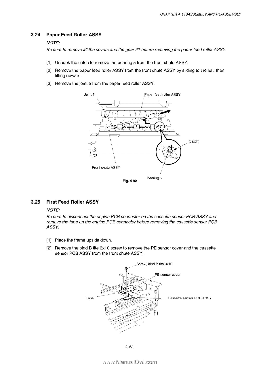
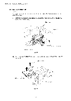
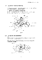
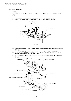
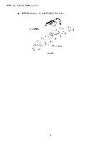
CHAPTER 4 DISASSEMBLY AND RE-ASSEMBLY 3.24 Paper Feed Roller ASSY NOTE: Be sure to remove all the covers and the gear 21 before removing the paper feed roller ASSY. (1) Unhook the catch to remove the bearing 5 from the front chute ASSY. (2) Remove the paper feed roller ASSY from the front chute ASSY by sliding to the left, then lifting upward. (3) Remove the joint 5 from the paper feed roller ASSY. Joint 5 J Paper feed roller ASSY r\ ,',..Y.,..•" • 0 'MI\ (catch) Front chute ASSY Fig. 4-92 Bearing 5 3.25 First Feed Roller ASSY NOTE: Be sure to disconnect the engine PCB connector on the cassette sensor PCB ASSY and remove the tape on the engine PCB connector before removing the cassette sensor PCB ASSY. (1) Place the frame upside down. (2) Remove the bind B tite 3x10 screw to remove the PE sensor cover and the cassette sensor PCB ASSY from the front chute ASSY. Screw, bind B tite 3x10 1 D. E sensor cover ( 1------ ^,------- c Tape ,-., , G__._,-- _.--4" Cassette sensor PCB ASSY ,)--------° 4-61
-
 1
1 -
2
-
3
-
4
-
5
-
6
-
7
-
8
-
9
-
10
-
11
-
12
-
13
-
14
-
15
-
16
-
17
-
18
-
19
-
20
-
21
-
22
-
23
-
24
-
25
-
26
-
27
-
28
-
29
-
30
-
31
-
32
-
33
-
34
-
35
-
36
-
37
-
38
-
39
-
40
-
41
-
42
-
43
-
44
-
45
-
46
-
47
-
48
-
49
-
50
-
51
-
52
-
53
-
54
-
55
-
56
-
57
-
58
-
59
-
60
-
61
-
62
-
63
-
64
-
65
-
66
-
67
-
68
-
69
-
70
-
71
-
72
-
73
-
74
-
75
-
76
-
77
-
78
-
79
-
80
-
81
-
82
-
83
-
84
-
85
-
86
-
87
-
88
-
89
-
90
-
91
-
92
-
93
-
94
-
95
-
96
-
97
-
98
-
99
-
100
-
101
-
102
-
103
-
104
-
105
-
106
-
107
-
108
-
109
-
110
-
111
-
112
-
113
-
114
-
115
-
116
-
117
-
118
-
119
-
120
-
121
-
122
-
123
-
124
-
125
-
126
-
127
-
128
-
129
-
130
-
131
-
132
-
133
-
134
-
135
-
136
-
137
-
138
-
139
-
140
-
141
-
142
-
143
-
144
-
145
-
146
-
147
-
148
-
149
-
150
-
151
-
 152
152 -
 153
153 -
 154
154 -
 155
155 -
 156
156 -
 157
157 -
 158
158 -
 159
159 -
 160
160 -
 161
161 -
 162
162 -
163
-
164
-
165
-
166
-
167
-
168
-
169
-
170
-
171
-
172
-
173
-
174
-
175
-
176
-
177
-
178
-
179
-
180
-
181
-
182
-
183
-
184
-
185
-
186
-
187
-
188
-
189
-
190
-
191
-
192
-
193
-
194
-
195
-
196
-
197
-
198
-
199
-
200
-
201
-
202
-
203
-
204
-
205
-
206
-
207
-
208
-
209
-
210
-
211
-
212
-
213
-
214
-
215
-
216
-
217
-
218
-
219
-
220
-
221
-
222
-
223
-
224
-
225
-
226
-
227
-
228
-
229
-
230
-
231
-
232
-
233
-
234
-
235
-
236
-
237
-
238
-
239
-
240
-
241
-
242
-
243
-
244
-
245
-
246
-
247
-
248
-
249
-
250
-
251
-
252
-
253
-
254
-
255
-
256
-
257
-
258
-
259
-
260
-
261
-
262
-
263
-
264
-
265
-
266
-
267
-
268
-
269
-
270
-
271
-
272
-
273
-
274
-
275
-
276
-
277
 |
 |