Brother International HL 1850 Service Manual - Page 5
Theory, Operation
 |
UPC - 012502603900
View all Brother International HL 1850 manuals
Add to My Manuals
Save this manual to your list of manuals |
Page 5 highlights
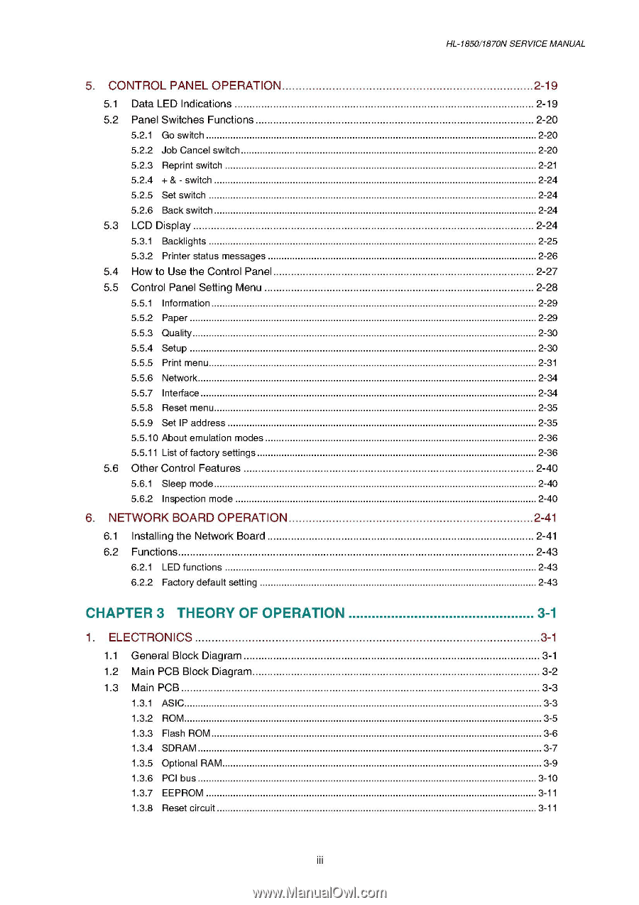
5. CONTROL PANEL OPERATION 5.1 Data LED Indications 5.2 Panel Switches Functions 5.2.1 Go switch 5.2.2 Job Cancel switch 5.2.3 Reprint switch 5.2.4 + & - switch 5.2.5 Set switch 5.2.6 Back switch 5.3 LCD Display 5.3.1 Backlights 5.3.2 Printer status messages 5.4 How to Use the Control Panel 5.5 Control Panel Setting Menu 5.5.1 Information 5.5.2 Paper 5.5.3 Quality 5.5.4 Setup 5.5.5 Print menu 5.5.6 Network 5.5.7 Interface 5.5.8 Reset menu 5.5.9 Set IP address 5.5.10 About emulation modes 5.5.11 List of factory settings 5.6 Other Control Features 5.6.1 Sleep mode 5.6.2 Inspection mode 6. NETWORK BOARD OPERATION 6.1 Installing the Network Board 6.2 Functions 6.2.1 LED functions 6.2.2 Factory default setting CHAPTER 3 THEORY OF OPERATION 1. ELECTRONICS 1.1 General Block Diagram 1.2 Main PCB Block Diagram 1.3 Main PCB 1.3.1 ASIC 1.3.2 ROM 1.3.3 Flash ROM 1.3.4 SDRAM 1.3.5 Optional RAM 1.3.6 PCI bus 1.3.7 EEPROM 1.3.8 Reset circuit iii HL-1850/1870N SERVICE MANUAL 2-19 2-19 2-20 2-20 2-20 2-21 2-24 2-24 2-24 2-24 2-25 2-26 2-27 2-28 2-29 2-29 2-30 2-30 2-31 2-34 2-34 2-35 2-35 2-36 2-36 2-40 2-40 2-40 2-41 2-41 2-43 2-43 2-43 3-1 3-1 3-1 3-2 3-3 3-3 3-5 3-6 3-7 3-9 3-10 3-11 3-11
-
 1
1 -
 2
2 -
 3
3 -
 4
4 -
 5
5 -
 6
6 -
 7
7 -
 8
8 -
 9
9 -
 10
10 -
 11
11 -
12
-
13
-
14
-
15
-
16
-
17
-
18
-
19
-
20
-
21
-
22
-
23
-
24
-
25
-
26
-
27
-
28
-
29
-
30
-
31
-
32
-
33
-
34
-
35
-
36
-
37
-
38
-
39
-
40
-
41
-
42
-
43
-
44
-
45
-
46
-
47
-
48
-
49
-
50
-
51
-
52
-
53
-
54
-
55
-
56
-
57
-
58
-
59
-
60
-
61
-
62
-
63
-
64
-
65
-
66
-
67
-
68
-
69
-
70
-
71
-
72
-
73
-
74
-
75
-
76
-
77
-
78
-
79
-
80
-
81
-
82
-
83
-
84
-
85
-
86
-
87
-
88
-
89
-
90
-
91
-
92
-
93
-
94
-
95
-
96
-
97
-
98
-
99
-
100
-
101
-
102
-
103
-
104
-
105
-
106
-
107
-
108
-
109
-
110
-
111
-
112
-
113
-
114
-
115
-
116
-
117
-
118
-
119
-
120
-
121
-
122
-
123
-
124
-
125
-
126
-
127
-
128
-
129
-
130
-
131
-
132
-
133
-
134
-
135
-
136
-
137
-
138
-
139
-
140
-
141
-
142
-
143
-
144
-
145
-
146
-
147
-
148
-
149
-
150
-
151
-
152
-
153
-
154
-
155
-
156
-
157
-
158
-
159
-
160
-
161
-
162
-
163
-
164
-
165
-
166
-
167
-
168
-
169
-
170
-
171
-
172
-
173
-
174
-
175
-
176
-
177
-
178
-
179
-
180
-
181
-
182
-
183
-
184
-
185
-
186
-
187
-
188
-
189
-
190
-
191
-
192
-
193
-
194
-
195
-
196
-
197
-
198
-
199
-
200
-
201
-
202
-
203
-
204
-
205
-
206
-
207
-
208
-
209
-
210
-
211
-
212
-
213
-
214
-
215
-
216
-
217
-
218
-
219
-
220
-
221
-
222
-
223
-
224
-
225
-
226
-
227
-
228
-
229
-
230
-
231
-
232
-
233
-
234
-
235
-
236
-
237
-
238
-
239
-
240
-
241
-
242
-
243
-
244
-
245
-
246
-
247
-
248
-
249
-
250
-
251
-
252
-
253
-
254
-
255
-
256
-
257
-
258
-
259
-
260
-
261
-
262
-
263
-
264
-
265
-
266
-
267
-
268
-
269
-
270
-
271
-
272
-
273
-
274
-
275
-
276
-
277
 |
 |