Brother International HL 1850 Service Manual - Page 154
DISASSEMBLY, ASSEMBLY, Engine, frame, Screws, voltage
 |
UPC - 012502603900
View all Brother International HL 1850 manuals
Add to My Manuals
Save this manual to your list of manuals |
Page 154 highlights
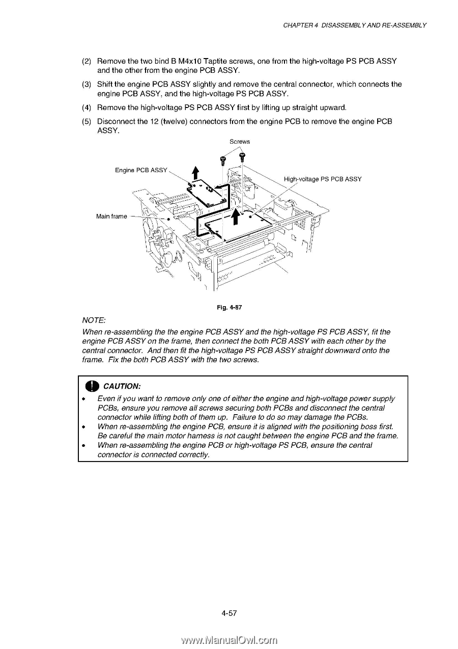
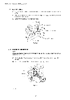
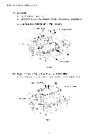
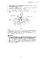
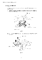
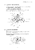
CHAPTER 4 DISASSEMBLY AND RE-ASSEMBLY (2) Remove the two bind B M4x10 Taptite screws, one from the high-voltage PS PCB ASSY and the other from the engine PCB ASSY. (3) Shift the engine PCB ASSY slightly and remove the central connector, which connects the engine PCB ASSY, and the high-voltage PS PCB ASSY. (4) Remove the high-voltage PS PCB ASSY first by lifting up straight upward. (5) Disconnect the 12 (twelve) connectors from the engine PCB to remove the engine PCB ASSY. Screws Engine PCB ASSY Main frame ,----- ) ) 7 > ,.. .e..... \O- High-voltage PS PCB ASSY 1 ' Fig. 4-87 NOTE: When re-assembling the the engine PCB ASSY and the high-voltage PS PCB ASSY, fit the engine PCB ASSY on the frame, then connect the both PCB ASSY with each other by the central connector. And then fit the high-voltage PS PCB ASSY straight downward onto the frame. Fix the both PCB ASSY with the two screws. CAUTION: • Even ifyou want to remove only one ofeither the engine andhigh-voltage power supply PCBs, ensure you remove all screws securing both PCBs and disconnect the central connector while lifting both of them up. Failure to do so may damage the PCBs. • When re-assembling the engine PCB, ensure it is aligned with the positioning boss first. Be careful the main motor harness is not caught between the engine PCB and the frame. • When re-assembling the engine PCB or high-voltage PS PCB, ensure the central connector is connected correctly. 0
-
 1
1 -
2
-
3
-
4
-
5
-
6
-
7
-
8
-
9
-
10
-
11
-
12
-
13
-
14
-
15
-
16
-
17
-
18
-
19
-
20
-
21
-
22
-
23
-
24
-
25
-
26
-
27
-
28
-
29
-
30
-
31
-
32
-
33
-
34
-
35
-
36
-
37
-
38
-
39
-
40
-
41
-
42
-
43
-
44
-
45
-
46
-
47
-
48
-
49
-
50
-
51
-
52
-
53
-
54
-
55
-
56
-
57
-
58
-
59
-
60
-
61
-
62
-
63
-
64
-
65
-
66
-
67
-
68
-
69
-
70
-
71
-
72
-
73
-
74
-
75
-
76
-
77
-
78
-
79
-
80
-
81
-
82
-
83
-
84
-
85
-
86
-
87
-
88
-
89
-
90
-
91
-
92
-
93
-
94
-
95
-
96
-
97
-
98
-
99
-
100
-
101
-
102
-
103
-
104
-
105
-
106
-
107
-
108
-
109
-
110
-
111
-
112
-
113
-
114
-
115
-
116
-
117
-
118
-
119
-
120
-
121
-
122
-
123
-
124
-
125
-
126
-
127
-
128
-
129
-
130
-
131
-
132
-
133
-
134
-
135
-
136
-
137
-
138
-
139
-
140
-
141
-
142
-
143
-
144
-
145
-
146
-
147
-
148
-
 149
149 -
 150
150 -
 151
151 -
 152
152 -
 153
153 -
 154
154 -
 155
155 -
 156
156 -
 157
157 -
 158
158 -
 159
159 -
160
-
161
-
162
-
163
-
164
-
165
-
166
-
167
-
168
-
169
-
170
-
171
-
172
-
173
-
174
-
175
-
176
-
177
-
178
-
179
-
180
-
181
-
182
-
183
-
184
-
185
-
186
-
187
-
188
-
189
-
190
-
191
-
192
-
193
-
194
-
195
-
196
-
197
-
198
-
199
-
200
-
201
-
202
-
203
-
204
-
205
-
206
-
207
-
208
-
209
-
210
-
211
-
212
-
213
-
214
-
215
-
216
-
217
-
218
-
219
-
220
-
221
-
222
-
223
-
224
-
225
-
226
-
227
-
228
-
229
-
230
-
231
-
232
-
233
-
234
-
235
-
236
-
237
-
238
-
239
-
240
-
241
-
242
-
243
-
244
-
245
-
246
-
247
-
248
-
249
-
250
-
251
-
252
-
253
-
254
-
255
-
256
-
257
-
258
-
259
-
260
-
261
-
262
-
263
-
264
-
265
-
266
-
267
-
268
-
269
-
270
-
271
-
272
-
273
-
274
-
275
-
276
-
277
 |
 |