Brother International HL 1850 Service Manual - Page 89
Engine
 |
UPC - 012502603900
View all Brother International HL 1850 manuals
Add to My Manuals
Save this manual to your list of manuals |
Page 89 highlights
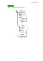
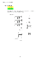
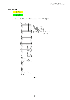
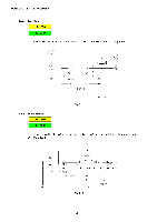
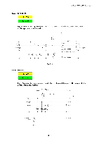
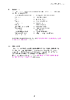
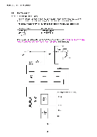
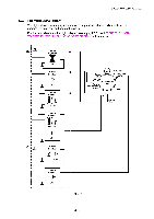
HL-1850/1870N SERVICE MANUAL 1.4 Engine PCB The gate array which transforms the serial signal from the main PCB into the parallel signal is mounted on the engine PCB. The engine PCB controls the following parts by using the transferred signal data; • Main motor • Fan motor • Thermistor • Polygon motor • Solenoid • High-voltage power supply • Toner sensor • Cover sensor • Front registration sensor • Rear registration sensor • Upper cassette sensor • Lower cassette sensor • Upper paper exit sensor . Lower paper exit sensor . Duplex tray sensor . Duplex lever sensor • Duplex cover sensor • Lower cassette exit sensor • Paper eject sensor • Fixing unit cover sensor • Multi-purpose tray paper exit sensor For the circuit diagram of the engine PCB, see APPENDIX 8. and 9. `ENGINE PCB CIRCUIT DIAGRAM, HL-1850/1870N' in this manual. 1.5 BR-net PCB The BR-net PCB is connected to the ASIC mounted on the main PCB through the PCI bus. The Ethernet controller, AM79C973AKC is mounted on the BR-net PCB. The controller incorporates the 10/100 Mbps physical interface which conforms to IEEE 802.3 and is connected with the external Ethernet through the RJ-45 connector. For the circuit diagram of the BR-net PCB, see APPENDIX 10. `NETWORK BOARD PCB CIRCUIT DIAGRAM, HL-1850/1870N' in this manual. 3-15
-
 1
1 -
2
-
3
-
4
-
5
-
6
-
7
-
8
-
9
-
10
-
11
-
12
-
13
-
14
-
15
-
16
-
17
-
18
-
19
-
20
-
21
-
22
-
23
-
24
-
25
-
26
-
27
-
28
-
29
-
30
-
31
-
32
-
33
-
34
-
35
-
36
-
37
-
38
-
39
-
40
-
41
-
42
-
43
-
44
-
45
-
46
-
47
-
48
-
49
-
50
-
51
-
52
-
53
-
54
-
55
-
56
-
57
-
58
-
59
-
60
-
61
-
62
-
63
-
64
-
65
-
66
-
67
-
68
-
69
-
70
-
71
-
72
-
73
-
74
-
75
-
76
-
77
-
78
-
79
-
80
-
81
-
82
-
83
-
 84
84 -
 85
85 -
 86
86 -
 87
87 -
 88
88 -
 89
89 -
 90
90 -
 91
91 -
 92
92 -
 93
93 -
 94
94 -
95
-
96
-
97
-
98
-
99
-
100
-
101
-
102
-
103
-
104
-
105
-
106
-
107
-
108
-
109
-
110
-
111
-
112
-
113
-
114
-
115
-
116
-
117
-
118
-
119
-
120
-
121
-
122
-
123
-
124
-
125
-
126
-
127
-
128
-
129
-
130
-
131
-
132
-
133
-
134
-
135
-
136
-
137
-
138
-
139
-
140
-
141
-
142
-
143
-
144
-
145
-
146
-
147
-
148
-
149
-
150
-
151
-
152
-
153
-
154
-
155
-
156
-
157
-
158
-
159
-
160
-
161
-
162
-
163
-
164
-
165
-
166
-
167
-
168
-
169
-
170
-
171
-
172
-
173
-
174
-
175
-
176
-
177
-
178
-
179
-
180
-
181
-
182
-
183
-
184
-
185
-
186
-
187
-
188
-
189
-
190
-
191
-
192
-
193
-
194
-
195
-
196
-
197
-
198
-
199
-
200
-
201
-
202
-
203
-
204
-
205
-
206
-
207
-
208
-
209
-
210
-
211
-
212
-
213
-
214
-
215
-
216
-
217
-
218
-
219
-
220
-
221
-
222
-
223
-
224
-
225
-
226
-
227
-
228
-
229
-
230
-
231
-
232
-
233
-
234
-
235
-
236
-
237
-
238
-
239
-
240
-
241
-
242
-
243
-
244
-
245
-
246
-
247
-
248
-
249
-
250
-
251
-
252
-
253
-
254
-
255
-
256
-
257
-
258
-
259
-
260
-
261
-
262
-
263
-
264
-
265
-
266
-
267
-
268
-
269
-
270
-
271
-
272
-
273
-
274
-
275
-
276
-
277
 |
 |