Brother International HL 1850 Service Manual - Page 129
Laser
 |
UPC - 012502603900
View all Brother International HL 1850 manuals
Add to My Manuals
Save this manual to your list of manuals |
Page 129 highlights
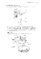
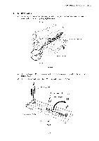
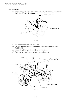
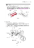
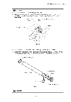
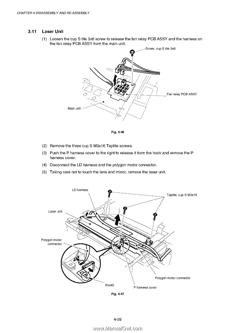
CHAPTER 4 DISASSEMBLY AND RE-ASSEMBLY 3.11 Laser Unit (1) Loosen the cup S tite 3x6 screw to release the fan relay PCB ASSY and the harness on the fan relay PCB ASSY from the main unit. Screw, cup S tite 3x6 Main unit Fan relay PCB ASSY Fig. 4-46 (2) Remove the three cup S M3x16 Taptite screws. (3) Push the P harness cover to the right to release it from the hook and remove the P harness cover. (4) Disconnect the LD harness and the polygon motor connector. (5) Taking care not to touch the lens and mirror, remove the laser unit. LD harness Laser unit Taptite, cup S M3x16 Polygon motor connector z N (hook) Fig. 4-47 Polygon motor connector P harness cover 4-28
-
 1
1 -
2
-
3
-
4
-
5
-
6
-
7
-
8
-
9
-
10
-
11
-
12
-
13
-
14
-
15
-
16
-
17
-
18
-
19
-
20
-
21
-
22
-
23
-
24
-
25
-
26
-
27
-
28
-
29
-
30
-
31
-
32
-
33
-
34
-
35
-
36
-
37
-
38
-
39
-
40
-
41
-
42
-
43
-
44
-
45
-
46
-
47
-
48
-
49
-
50
-
51
-
52
-
53
-
54
-
55
-
56
-
57
-
58
-
59
-
60
-
61
-
62
-
63
-
64
-
65
-
66
-
67
-
68
-
69
-
70
-
71
-
72
-
73
-
74
-
75
-
76
-
77
-
78
-
79
-
80
-
81
-
82
-
83
-
84
-
85
-
86
-
87
-
88
-
89
-
90
-
91
-
92
-
93
-
94
-
95
-
96
-
97
-
98
-
99
-
100
-
101
-
102
-
103
-
104
-
105
-
106
-
107
-
108
-
109
-
110
-
111
-
112
-
113
-
114
-
115
-
116
-
117
-
118
-
119
-
120
-
121
-
122
-
123
-
 124
124 -
 125
125 -
 126
126 -
 127
127 -
 128
128 -
 129
129 -
 130
130 -
 131
131 -
 132
132 -
 133
133 -
 134
134 -
135
-
136
-
137
-
138
-
139
-
140
-
141
-
142
-
143
-
144
-
145
-
146
-
147
-
148
-
149
-
150
-
151
-
152
-
153
-
154
-
155
-
156
-
157
-
158
-
159
-
160
-
161
-
162
-
163
-
164
-
165
-
166
-
167
-
168
-
169
-
170
-
171
-
172
-
173
-
174
-
175
-
176
-
177
-
178
-
179
-
180
-
181
-
182
-
183
-
184
-
185
-
186
-
187
-
188
-
189
-
190
-
191
-
192
-
193
-
194
-
195
-
196
-
197
-
198
-
199
-
200
-
201
-
202
-
203
-
204
-
205
-
206
-
207
-
208
-
209
-
210
-
211
-
212
-
213
-
214
-
215
-
216
-
217
-
218
-
219
-
220
-
221
-
222
-
223
-
224
-
225
-
226
-
227
-
228
-
229
-
230
-
231
-
232
-
233
-
234
-
235
-
236
-
237
-
238
-
239
-
240
-
241
-
242
-
243
-
244
-
245
-
246
-
247
-
248
-
249
-
250
-
251
-
252
-
253
-
254
-
255
-
256
-
257
-
258
-
259
-
260
-
261
-
262
-
263
-
264
-
265
-
266
-
267
-
268
-
269
-
270
-
271
-
272
-
273
-
274
-
275
-
276
-
277
 |
 |
CHAPTER
4
DISASSEMBLY
AND
RE
-ASSEMBLY
3.11
Laser
Unit
(1)
Loosen
the
cup
S
tite
3x6
screw
to
release
the
fan
relay
PCB
ASSY
and
the
harness
on
the
fan
relay
PCB
ASSY
from
the
main
unit.
Screw,
cup
S
tite
3x6
Fan
relay
PCB
ASSY
Main
unit
Fig.
4-46
(2)
Remove
the
three
cup
S
M3x16
Taptite
screws.
(3)
Push
the
P
harness
cover
to
the
right
to
release
it
from
the
hook
and
remove
the
P
harness
cover.
(4)
Disconnect
the
LD
harness
and
the
polygon
motor
connector.
(5)
Taking
care
not
to
touch
the
lens
and
mirror,
remove
the
laser
unit.
LD
harness
Taptite,
cup
S
M3x1
6
Laser
unit
Polygon
motor
connector
z
N
Polygon
motor
connector
(hook)
Fig.
4-47
P
harness
cover
4-28