Brother International HL 1850 Service Manual - Page 232
Inspection
 |
UPC - 012502603900
View all Brother International HL 1850 manuals
Add to My Manuals
Save this manual to your list of manuals |
Page 232 highlights
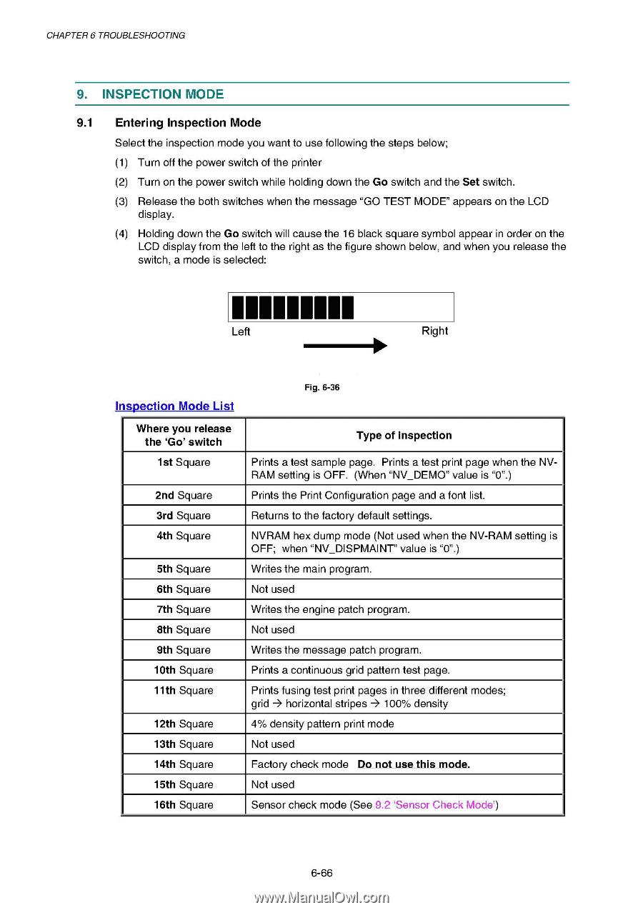
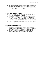
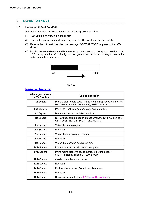
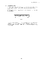
CHAPTER 6 TROUBLESHOOTING 9. INSPECTION MODE 9.1 Entering Inspection Mode Select the inspection mode you want to use following the steps below; (1) Turn off the power switch of the printer (2) Turn on the power switch while holding down the Go switch and the Set switch. (3) Release the both switches when the message "GO TEST MODE" appears on the LCD display. (4) Holding down the Go switch will cause the 16 black square symbol appear in order on the LCD display from the left to the right as the figure shown below, and when you release the switch, a mode is selected: 11111E11 Left Right Inspection Mode List Where you release the `Go' switch 1st Square 2nd Square 3rd Square 4th Square 5th Square 6th Square 7th Square 8th Square 9th Square 10th Square 11th Square 12th Square 13th Square 14th Square 15th Square 16th Square Fig. 6-36 Type of inspection Prints a test sample page. Prints a test print page when the NVRAM setting is OFF. (When "NV_DEMO" value is "0".) Prints the Print Configuration page and a font list. Returns to the factory default settings. NVRAM hex dump mode (Not used when the NV-RAM setting is OFF; when "NV_DISPMAINT" value is "0".) Writes the main program. Not used Writes the engine patch program. Not used Writes the message patch program. Prints a continuous grid pattern test page. Prints fusing test print pages in three different modes; grid 4 horizontal stripes 4 100% density 4% density pattern print mode Not used Factory check mode Do not use this mode. Not used Sensor check mode (See 9.2 `Sensor Check Mode') 6-66
-
 1
1 -
2
-
3
-
4
-
5
-
6
-
7
-
8
-
9
-
10
-
11
-
12
-
13
-
14
-
15
-
16
-
17
-
18
-
19
-
20
-
21
-
22
-
23
-
24
-
25
-
26
-
27
-
28
-
29
-
30
-
31
-
32
-
33
-
34
-
35
-
36
-
37
-
38
-
39
-
40
-
41
-
42
-
43
-
44
-
45
-
46
-
47
-
48
-
49
-
50
-
51
-
52
-
53
-
54
-
55
-
56
-
57
-
58
-
59
-
60
-
61
-
62
-
63
-
64
-
65
-
66
-
67
-
68
-
69
-
70
-
71
-
72
-
73
-
74
-
75
-
76
-
77
-
78
-
79
-
80
-
81
-
82
-
83
-
84
-
85
-
86
-
87
-
88
-
89
-
90
-
91
-
92
-
93
-
94
-
95
-
96
-
97
-
98
-
99
-
100
-
101
-
102
-
103
-
104
-
105
-
106
-
107
-
108
-
109
-
110
-
111
-
112
-
113
-
114
-
115
-
116
-
117
-
118
-
119
-
120
-
121
-
122
-
123
-
124
-
125
-
126
-
127
-
128
-
129
-
130
-
131
-
132
-
133
-
134
-
135
-
136
-
137
-
138
-
139
-
140
-
141
-
142
-
143
-
144
-
145
-
146
-
147
-
148
-
149
-
150
-
151
-
152
-
153
-
154
-
155
-
156
-
157
-
158
-
159
-
160
-
161
-
162
-
163
-
164
-
165
-
166
-
167
-
168
-
169
-
170
-
171
-
172
-
173
-
174
-
175
-
176
-
177
-
178
-
179
-
180
-
181
-
182
-
183
-
184
-
185
-
186
-
187
-
188
-
189
-
190
-
191
-
192
-
193
-
194
-
195
-
196
-
197
-
198
-
199
-
200
-
201
-
202
-
203
-
204
-
205
-
206
-
207
-
208
-
209
-
210
-
211
-
212
-
213
-
214
-
215
-
216
-
217
-
218
-
219
-
220
-
221
-
222
-
223
-
224
-
225
-
226
-
 227
227 -
 228
228 -
 229
229 -
 230
230 -
 231
231 -
 232
232 -
 233
233 -
 234
234 -
 235
235 -
 236
236 -
 237
237 -
238
-
239
-
240
-
241
-
242
-
243
-
244
-
245
-
246
-
247
-
248
-
249
-
250
-
251
-
252
-
253
-
254
-
255
-
256
-
257
-
258
-
259
-
260
-
261
-
262
-
263
-
264
-
265
-
266
-
267
-
268
-
269
-
270
-
271
-
272
-
273
-
274
-
275
-
276
-
277
 |
 |