HP 6125XLG R2306-HP 6125XLG Blade Switch Layer 2 - LAN Switching Command Refer - Page 81
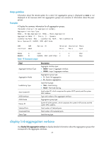
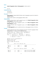
display link-aggregation summary, Syntax, Views, Predefined user roles
 |
View all HP 6125XLG manuals
Add to My Manuals
Save this manual to your list of manuals |
Page 81 highlights
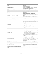
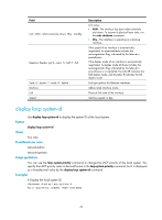
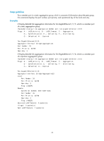
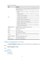
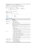
Table 16 Command output Field Flags Aggregate Interface Local Oper-key Flag Remote System ID Received LACP Packets Illegal Sent LACP Packets Description LACP state flags. This field is 1 byte long, represented by ABCDEFGH from the least significant bit to the most significant bit. The letter is present when its bit is 1 and absent when its bit is 0. • A-Indicates whether LACP is enabled. 1 indicates enabled, and 0 indicates disabled. • B-Indicates the LACP short or long timeout. 1 indicates short timeout, and 0 indicates long timeout. • C-Indicates whether the sending system considers that the link is aggregatable. 1 indicates yes, and 0 indicates no. • D-Indicates whether the sending system considers that the link is synchronized. 1 indicates yes, and 0 indicates no. • E-Indicates whether the sending system considers that the incoming frames are collected. 1 indicates yes, and 0 indicates no. • F-Indicates whether the sending system considers that the outgoing frames are distributed. 1 indicates yes, and 0 indicates no. • G-Indicates whether the sending system receives frames in the default state. 1 indicates yes, and 0 indicates no. • H-Indicates whether the sending system receives frames in the expired state. 1 indicates yes, and 0 indicates no. Aggregate interface to which the member port belongs. Information about the local end. Operational key. LACP protocol state flag. Information about the remote end. Remote end system ID, comprising the system LACP priority and the system MAC address. Total number of LACP packets received. Total number of illegal packets. Total number of LACP packets sent. display link-aggregation summary Use display link-aggregation summary to display the summary information for all aggregation groups. Syntax display link-aggregation summary Views Any view Predefined user roles network-admin network-operator 74
-
 1
1 -
2
-
3
-
4
-
5
-
6
-
7
-
8
-
9
-
10
-
11
-
12
-
13
-
14
-
15
-
16
-
17
-
18
-
19
-
20
-
21
-
22
-
23
-
24
-
25
-
26
-
27
-
28
-
29
-
30
-
31
-
32
-
33
-
34
-
35
-
36
-
37
-
38
-
39
-
40
-
41
-
42
-
43
-
44
-
45
-
46
-
47
-
48
-
49
-
50
-
51
-
52
-
53
-
54
-
55
-
56
-
57
-
58
-
59
-
60
-
61
-
62
-
63
-
64
-
65
-
66
-
67
-
68
-
69
-
70
-
71
-
72
-
73
-
74
-
75
-
 76
76 -
 77
77 -
 78
78 -
 79
79 -
 80
80 -
 81
81 -
 82
82 -
 83
83 -
 84
84 -
 85
85 -
 86
86 -
87
-
88
-
89
-
90
-
91
-
92
-
93
-
94
-
95
-
96
-
97
-
98
-
99
-
100
-
101
-
102
-
103
-
104
-
105
-
106
-
107
-
108
-
109
-
110
-
111
-
112
-
113
-
114
-
115
-
116
-
117
-
118
-
119
-
120
-
121
-
122
-
123
-
124
-
125
-
126
-
127
-
128
-
129
-
130
-
131
-
132
-
133
-
134
-
135
-
136
-
137
-
138
-
139
-
140
-
141
-
142
-
143
-
144
-
145
-
146
-
147
-
148
-
149
-
150
-
151
-
152
-
153
-
154
-
155
-
156
-
157
-
158
-
159
-
160
-
161
-
162
-
163
-
164
-
165
-
166
-
167
-
168
-
169
-
170
-
171
-
172
-
173
-
174
-
175
-
176
-
177
-
178
-
179
-
180
-
181
-
182
-
183
-
184
-
185
-
186
-
187
-
188
-
189
-
190
-
191
-
192
-
193
-
194
-
195
-
196
-
197
-
198
-
199
-
200
-
201
-
202
-
203
-
204
-
205
-
206
-
207
-
208
-
209
-
210
-
211
-
212
-
213
-
214
-
215
-
216
-
217
-
218
-
219
-
220
 |
 |
