HP NetServer AA 4000 HP NetServer AA 6200 Solution Release 3.0 Administrator&a - Page 243
Replacing a CE, Updating MIC BIOS, FPGA, and Microcode, identical
 |
View all HP NetServer AA 4000 manuals
Add to My Manuals
Save this manual to your list of manuals |
Page 243 highlights
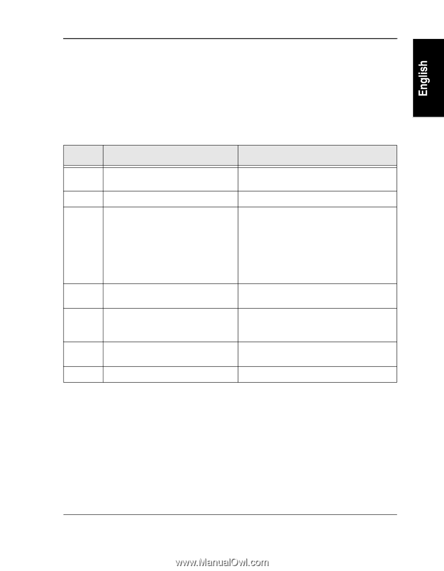
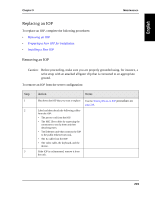
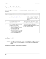
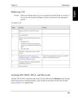
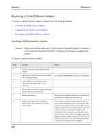
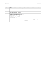
Chapter 9 Maintenance Replacing a CE Caution: Before proceeding, make sure you are properly grounded using, for instance, a wrist strap with an attached alligator clip that is connected to an appropriate ground To replace a CE: Step 1 2 3 4 5 6 7 Action Notes Shut down the CE as described on page 213. Power off the CE. Detach and label the following cables from the CE: • The power cord. • The MIC fiber cables by squeezing the connectors to unclip them and detaching them. • The video cable. If the CE is rackmounted, remove it from the rack. Prepare the new CE for installation, as described in Chapter 1 of the HP NetServer AA Solution Installation Guide. If required, fasten the rackmount brackets and install it in the rack. Power up the CE. Follow the procedure given in Chapter 2 of the HP NetServer AA Installation Guide. Updating MIC BIOS, FPGA, and Microcode The MIC BIOS, FPGA, and microcode on the CEs and IOPs must be identical on all CEs and IOPs for the server to function properly. If any of these do not match, use the MTCFLASH Utility (Chapter 7) to upgrade them. 227
-
 1
1 -
2
-
3
-
4
-
5
-
6
-
7
-
8
-
9
-
10
-
11
-
12
-
13
-
14
-
15
-
16
-
17
-
18
-
19
-
20
-
21
-
22
-
23
-
24
-
25
-
26
-
27
-
28
-
29
-
30
-
31
-
32
-
33
-
34
-
35
-
36
-
37
-
38
-
39
-
40
-
41
-
42
-
43
-
44
-
45
-
46
-
47
-
48
-
49
-
50
-
51
-
52
-
53
-
54
-
55
-
56
-
57
-
58
-
59
-
60
-
61
-
62
-
63
-
64
-
65
-
66
-
67
-
68
-
69
-
70
-
71
-
72
-
73
-
74
-
75
-
76
-
77
-
78
-
79
-
80
-
81
-
82
-
83
-
84
-
85
-
86
-
87
-
88
-
89
-
90
-
91
-
92
-
93
-
94
-
95
-
96
-
97
-
98
-
99
-
100
-
101
-
102
-
103
-
104
-
105
-
106
-
107
-
108
-
109
-
110
-
111
-
112
-
113
-
114
-
115
-
116
-
117
-
118
-
119
-
120
-
121
-
122
-
123
-
124
-
125
-
126
-
127
-
128
-
129
-
130
-
131
-
132
-
133
-
134
-
135
-
136
-
137
-
138
-
139
-
140
-
141
-
142
-
143
-
144
-
145
-
146
-
147
-
148
-
149
-
150
-
151
-
152
-
153
-
154
-
155
-
156
-
157
-
158
-
159
-
160
-
161
-
162
-
163
-
164
-
165
-
166
-
167
-
168
-
169
-
170
-
171
-
172
-
173
-
174
-
175
-
176
-
177
-
178
-
179
-
180
-
181
-
182
-
183
-
184
-
185
-
186
-
187
-
188
-
189
-
190
-
191
-
192
-
193
-
194
-
195
-
196
-
197
-
198
-
199
-
200
-
201
-
202
-
203
-
204
-
205
-
206
-
207
-
208
-
209
-
210
-
211
-
212
-
213
-
214
-
215
-
216
-
217
-
218
-
219
-
220
-
221
-
222
-
223
-
224
-
225
-
226
-
227
-
228
-
229
-
230
-
231
-
232
-
233
-
234
-
235
-
236
-
237
-
 238
238 -
 239
239 -
 240
240 -
 241
241 -
 242
242 -
 243
243 -
 244
244 -
 245
245 -
 246
246 -
 247
247 -
 248
248 -
249
-
250
-
251
-
252
-
253
-
254
-
255
-
256
-
257
-
258
-
259
-
260
-
261
-
262
-
263
-
264
-
265
-
266
-
267
-
268
-
269
-
270
-
271
-
272
-
273
-
274
-
275
-
276
-
277
-
278
-
279
-
280
-
281
 |
 |