HP NetServer AA 4000 HP NetServer AA 6200 Solution Release 3.0 Administrator&a - Page 34
Overview of IOP Boot Process, Appendix B
 |
View all HP NetServer AA 4000 manuals
Add to My Manuals
Save this manual to your list of manuals |
Page 34 highlights
Chapter 2 HP NetServer AA Overview Figure 2-3 Overview of IOP Boot Process After the IOPs complete their boot process, the CEs boot: one CE loads the Windows NT operating system; then the other CE is synchronized so that both CEs perform all CPU and memory functions in a tightly coupled manner. This ensures that in the event of a CPU or memory failure, the server operating system provides continuous computing without any loss of context. After the CE boot process completes, the server is available for use. For an IOP to service the CE boot request, it must have completed boot, as shown in Figure 2-3 and described in Appendix B. The CE boot process is summarized in Figure 2-4. A detailed CE boot process flowchart is in Appendix B. 18
-
 1
1 -
2
-
3
-
4
-
5
-
6
-
7
-
8
-
9
-
10
-
11
-
12
-
13
-
14
-
15
-
16
-
17
-
18
-
19
-
20
-
21
-
22
-
23
-
24
-
25
-
26
-
27
-
28
-
 29
29 -
 30
30 -
 31
31 -
 32
32 -
 33
33 -
 34
34 -
 35
35 -
 36
36 -
 37
37 -
 38
38 -
 39
39 -
40
-
41
-
42
-
43
-
44
-
45
-
46
-
47
-
48
-
49
-
50
-
51
-
52
-
53
-
54
-
55
-
56
-
57
-
58
-
59
-
60
-
61
-
62
-
63
-
64
-
65
-
66
-
67
-
68
-
69
-
70
-
71
-
72
-
73
-
74
-
75
-
76
-
77
-
78
-
79
-
80
-
81
-
82
-
83
-
84
-
85
-
86
-
87
-
88
-
89
-
90
-
91
-
92
-
93
-
94
-
95
-
96
-
97
-
98
-
99
-
100
-
101
-
102
-
103
-
104
-
105
-
106
-
107
-
108
-
109
-
110
-
111
-
112
-
113
-
114
-
115
-
116
-
117
-
118
-
119
-
120
-
121
-
122
-
123
-
124
-
125
-
126
-
127
-
128
-
129
-
130
-
131
-
132
-
133
-
134
-
135
-
136
-
137
-
138
-
139
-
140
-
141
-
142
-
143
-
144
-
145
-
146
-
147
-
148
-
149
-
150
-
151
-
152
-
153
-
154
-
155
-
156
-
157
-
158
-
159
-
160
-
161
-
162
-
163
-
164
-
165
-
166
-
167
-
168
-
169
-
170
-
171
-
172
-
173
-
174
-
175
-
176
-
177
-
178
-
179
-
180
-
181
-
182
-
183
-
184
-
185
-
186
-
187
-
188
-
189
-
190
-
191
-
192
-
193
-
194
-
195
-
196
-
197
-
198
-
199
-
200
-
201
-
202
-
203
-
204
-
205
-
206
-
207
-
208
-
209
-
210
-
211
-
212
-
213
-
214
-
215
-
216
-
217
-
218
-
219
-
220
-
221
-
222
-
223
-
224
-
225
-
226
-
227
-
228
-
229
-
230
-
231
-
232
-
233
-
234
-
235
-
236
-
237
-
238
-
239
-
240
-
241
-
242
-
243
-
244
-
245
-
246
-
247
-
248
-
249
-
250
-
251
-
252
-
253
-
254
-
255
-
256
-
257
-
258
-
259
-
260
-
261
-
262
-
263
-
264
-
265
-
266
-
267
-
268
-
269
-
270
-
271
-
272
-
273
-
274
-
275
-
276
-
277
-
278
-
279
-
280
-
281
 |
 |

Chapter 2
HP NetServer AA Overview
18
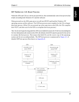
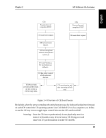
Figure 2-3
Overview of IOP Boot Process
After the IOPs complete their boot process, the CEs boot: one CE loads the Windows NT
operating system; then the other CE is synchronized so that both CEs perform all CPU and
memory functions in a tightly coupled manner. This ensures that in the event of a CPU or
memory failure, the server operating system provides continuous computing without any loss
of context. After the CE boot process completes, the server is available for use. For an IOP to
service the CE boot request, it must have completed boot, as shown in
Figure 2-3
and described
in
Appendix B
.
The CE boot process is summarized in
Figure 2-4
. A detailed CE boot process flowchart is in
Appendix B
.