HP NetServer AA 4000 HP NetServer AA 6200 Solution Release 3.0 Administrator&a - Page 41
Interconnect States, IOP States Continued
 |
View all HP NetServer AA 4000 manuals
Add to My Manuals
Save this manual to your list of manuals |
Page 41 highlights
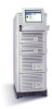
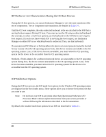
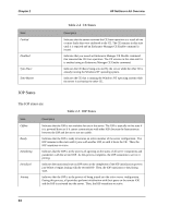
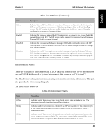
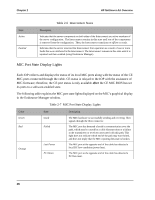
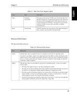
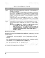
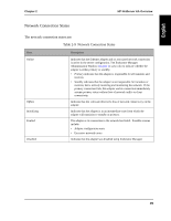
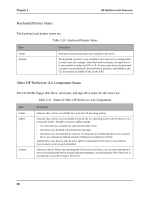
Chapter 2 HP NetServer AA Overview State Active Faulted Disabled Shutdown Table 2-5 IOP States (Continued) Description Indicates that the IOP is a fully active member of the server configuration. In this state, the IOP serves I/O requests from any active CE(s) and participates fully in all fault handling events. The IOP remains in this state until it is shutdown, disabled, or removed from the configuration as the result of a system failure. Indicates that the server removed the IOP from operation as a result of one or more faults that were attributed to the IOP. The IOP remains in this state until it is repaired and an Endurance Manager IOP Enable command is issued. Indicates that you issued an Endurance Manager IOP Disable command to remove the IOP from operation. The IOP remains in this state until it is enabled using an Endurance Manager IOP Enable command. Indicates that the IOP is being shut down either because you issued an Endurance Manager IOP Shutdown command, or because a fault occurred that requires the server to remove the IOP from the configuration. The IOP remains in this state only as long as it takes to properly shut down the Windows NT operating system on the IOP. Interconnect States There are two types of Interconnects: an IL (IOP link) that connects one IOP to the other IOP, and an ESI (HP NetServer AA System Interconnect) that connects an IOP to the CE. The IL cables provide a path for communicating system states and status information. This path also provides the mirror copy data path. The Interconnect states are: Table 2-6 Interconnect States State Offline Ready Online Description Indicates that the Interconnect is not in use by the server, but is available for use. The Interconnect typically transitions to ready from this state. Indicates that the Interconnect was activated by an IOP and is waiting for the component (CE or IOP) at the other end of the interconnect to also activate the Interconnect. Then, it transitions to online. Indicates that the Interconnect is in use and communication can be performed between the server components connected by it. The Interconnect remains in this state until the server activates the remote component. Then, the Interconnect transitions to active. 25
-
 1
1 -
2
-
3
-
4
-
5
-
6
-
7
-
8
-
9
-
10
-
11
-
12
-
13
-
14
-
15
-
16
-
17
-
18
-
19
-
20
-
21
-
22
-
23
-
24
-
25
-
26
-
27
-
28
-
29
-
30
-
31
-
32
-
33
-
34
-
35
-
 36
36 -
 37
37 -
 38
38 -
 39
39 -
 40
40 -
 41
41 -
 42
42 -
 43
43 -
 44
44 -
 45
45 -
 46
46 -
47
-
48
-
49
-
50
-
51
-
52
-
53
-
54
-
55
-
56
-
57
-
58
-
59
-
60
-
61
-
62
-
63
-
64
-
65
-
66
-
67
-
68
-
69
-
70
-
71
-
72
-
73
-
74
-
75
-
76
-
77
-
78
-
79
-
80
-
81
-
82
-
83
-
84
-
85
-
86
-
87
-
88
-
89
-
90
-
91
-
92
-
93
-
94
-
95
-
96
-
97
-
98
-
99
-
100
-
101
-
102
-
103
-
104
-
105
-
106
-
107
-
108
-
109
-
110
-
111
-
112
-
113
-
114
-
115
-
116
-
117
-
118
-
119
-
120
-
121
-
122
-
123
-
124
-
125
-
126
-
127
-
128
-
129
-
130
-
131
-
132
-
133
-
134
-
135
-
136
-
137
-
138
-
139
-
140
-
141
-
142
-
143
-
144
-
145
-
146
-
147
-
148
-
149
-
150
-
151
-
152
-
153
-
154
-
155
-
156
-
157
-
158
-
159
-
160
-
161
-
162
-
163
-
164
-
165
-
166
-
167
-
168
-
169
-
170
-
171
-
172
-
173
-
174
-
175
-
176
-
177
-
178
-
179
-
180
-
181
-
182
-
183
-
184
-
185
-
186
-
187
-
188
-
189
-
190
-
191
-
192
-
193
-
194
-
195
-
196
-
197
-
198
-
199
-
200
-
201
-
202
-
203
-
204
-
205
-
206
-
207
-
208
-
209
-
210
-
211
-
212
-
213
-
214
-
215
-
216
-
217
-
218
-
219
-
220
-
221
-
222
-
223
-
224
-
225
-
226
-
227
-
228
-
229
-
230
-
231
-
232
-
233
-
234
-
235
-
236
-
237
-
238
-
239
-
240
-
241
-
242
-
243
-
244
-
245
-
246
-
247
-
248
-
249
-
250
-
251
-
252
-
253
-
254
-
255
-
256
-
257
-
258
-
259
-
260
-
261
-
262
-
263
-
264
-
265
-
266
-
267
-
268
-
269
-
270
-
271
-
272
-
273
-
274
-
275
-
276
-
277
-
278
-
279
-
280
-
281
 |
 |