Yamaha AW16G Owner's Manual - Page 159
Using the test tone oscillator
 |
View all Yamaha AW16G manuals
Add to My Manuals
Save this manual to your list of manuals |
Page 159 highlights
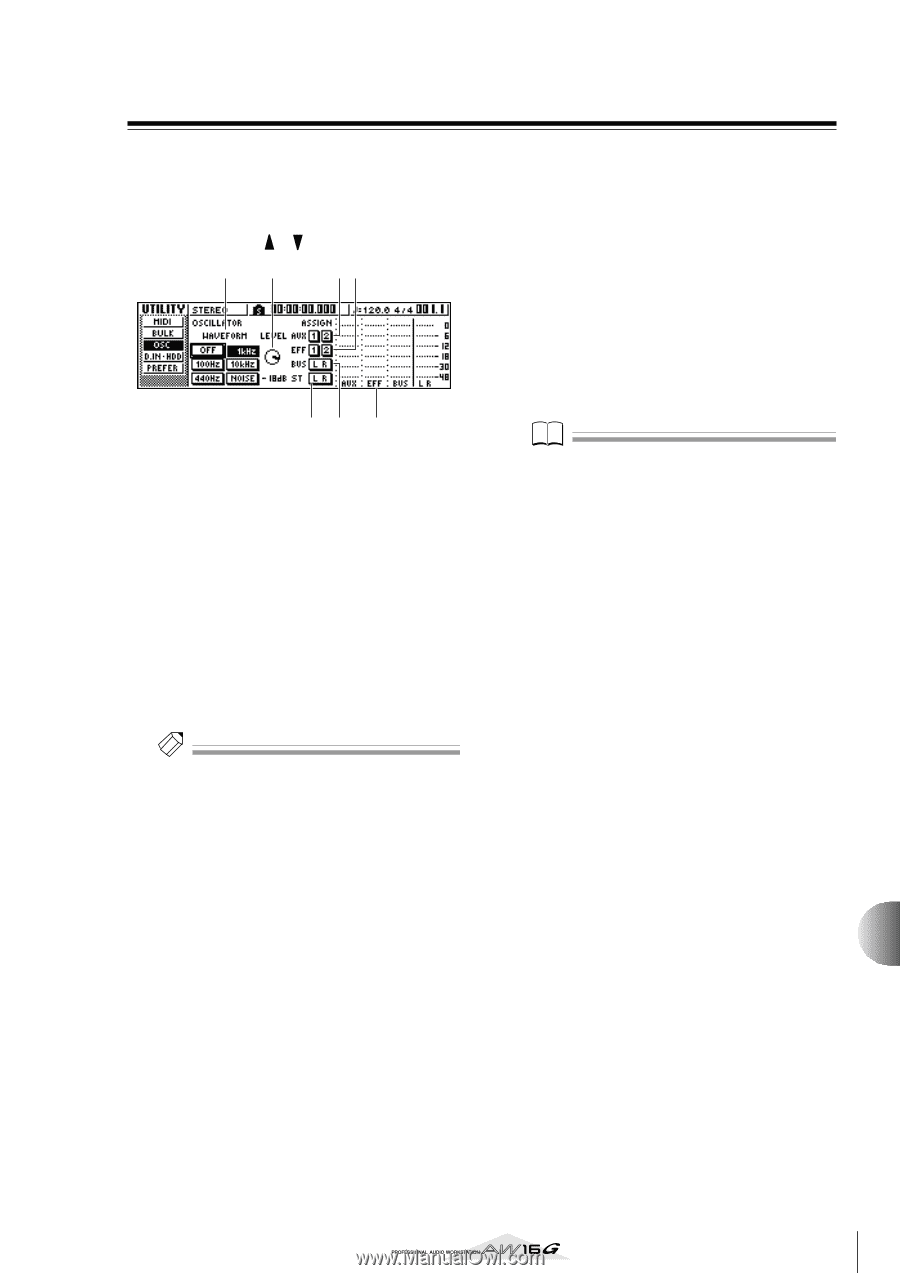
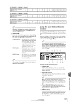
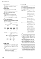
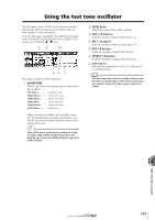
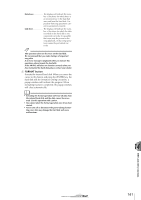
Using the test tone oscillator The OSC page of the UTILITY screen lets you send the signal of the AW16G's built-in test oscillator (the test tone oscillator) to the desired bus. To access this page, repeatedly press the Work Navigate section [UTILITY] key or hold down the [UTILITY] key and use the CURSOR [ ]/[ ] keys. 12 34 65 7 This page contains the following items. 1 WAVEFORM Selects one of the following signals for output from the oscillator. OFF button Oscillator is off 100Hz button 100 Hz sine wave 440Hz button 440 Hz sine wave 1kHz button 1 kHz sine wave 10 kHz button 10 kHz sine wave NOISE button White noise When you turn on a button, the oscillator output will immediately be sent to the specified bus. Use the 3-6 buttons to specify the bus to which the signal will be sent. Tip! If the LEVEL knob is raised when you output the oscillator signal, a high volume level may be produced suddenly. Be sure to lower the LEVEL knob before you switch on the oscillator. B LEVEL knob Adjusts the output level of the oscillator. C AUX 1/2 buttons Send the oscillator output to AUX buses 1/2. D EFF 1/2 buttons Send the oscillator output to effect buses 1/2. E BUS L R button Sends the oscillator output to the L/R bus. F STEREO L R button Sends the oscillator output to the stereo bus. G Level meter Indicates the output level of AUX 1/2, effect bus 1/ 2, and the L/R bus. Note Sine waves and white noise have a higher sound pressure than they perceptually appear. These signals may damage your speakers if played at a high volume, so please use caution. 14 MIDI and utility functions 159
-
 1
1 -
2
-
3
-
4
-
5
-
6
-
7
-
8
-
9
-
10
-
11
-
12
-
13
-
14
-
15
-
16
-
17
-
18
-
19
-
20
-
21
-
22
-
23
-
24
-
25
-
26
-
27
-
28
-
29
-
30
-
31
-
32
-
33
-
34
-
35
-
36
-
37
-
38
-
39
-
40
-
41
-
42
-
43
-
44
-
45
-
46
-
47
-
48
-
49
-
50
-
51
-
52
-
53
-
54
-
55
-
56
-
57
-
58
-
59
-
60
-
61
-
62
-
63
-
64
-
65
-
66
-
67
-
68
-
69
-
70
-
71
-
72
-
73
-
74
-
75
-
76
-
77
-
78
-
79
-
80
-
81
-
82
-
83
-
84
-
85
-
86
-
87
-
88
-
89
-
90
-
91
-
92
-
93
-
94
-
95
-
96
-
97
-
98
-
99
-
100
-
101
-
102
-
103
-
104
-
105
-
106
-
107
-
108
-
109
-
110
-
111
-
112
-
113
-
114
-
115
-
116
-
117
-
118
-
119
-
120
-
121
-
122
-
123
-
124
-
125
-
126
-
127
-
128
-
129
-
130
-
131
-
132
-
133
-
134
-
135
-
136
-
137
-
138
-
139
-
140
-
141
-
142
-
143
-
144
-
145
-
146
-
147
-
148
-
149
-
150
-
151
-
152
-
153
-
 154
154 -
 155
155 -
 156
156 -
 157
157 -
 158
158 -
 159
159 -
 160
160 -
 161
161 -
 162
162 -
 163
163 -
 164
164 -
165
-
166
-
167
-
168
-
169
-
170
-
171
-
172
-
173
-
174
-
175
-
176
-
177
-
178
-
179
-
180
-
181
-
182
-
183
-
184
-
185
-
186
-
187
-
188
-
189
-
190
-
191
-
192
-
193
-
194
-
195
-
196
-
197
-
198
-
199
-
200
-
201
-
202
-
203
-
204
-
205
-
206
-
207
-
208
-
209
-
210
-
211
-
212
-
213
-
214
-
215
-
216
-
217
-
218
-
219
 |
 |