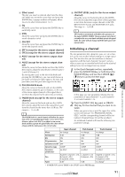
Yamaha AW16G Owner's Manual - Page 93
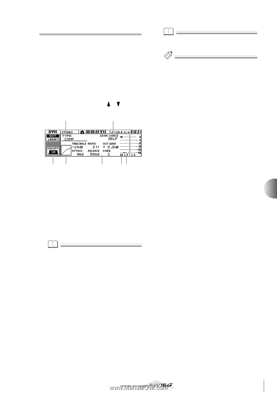
Editing the dynamics parameters, ON/OFF button, Response curve, KEYIN SOURCE, GR Gain Reduction
 |
View all Yamaha AW16G manuals
Add to My Manuals
Save this manual to your list of manuals |
Page 93 highlights
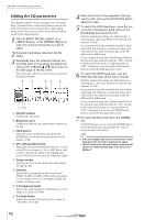
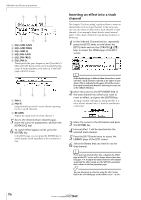
Editing the dynamics parameters You can perform detailed editing of the dynamics parameters in the same way as for the EQ parameters. 1 Press an [INPUT SEL] key, a pad 1-4, a [TRACK SEL] key, or the [STEREO SEL] key to select the channel whose dynamics parameters you want to edit. 2 From the dynamics library, recall the settings that are closest to what you have in mind. 3 Repeatedly press the Selected Channel section [DYN] knob or hold down the [DYN] knob and use the CURSOR [ ]/[ ] keys to access the EDIT page of the DYN screen. 2 4 13 7 56 1 ON/OFF button Switches dynamics on/off. B TYPE Indicates the currently selected dynamics type. The displayed indication has the following meaning. COMP Compressor EXPAND Expander GATE Gate COMPAND-H Compander (hard) COMPAND-S Compander (soft) DUCKING Ducking Note You cannot change the dynamics type in this page. If you want to use a different type, you must recall library settings that use the desired type. C Response curve This graph indicates the approximate response of dynamics settings. The horizontal axis of the graph is the input level, and the vertical axis is the output level. D KEYIN SOURCE Selects one of the following as the trigger signal (key-in signal) that will control dynamics processing. SELF The post-EQ signal of the currently selected channel LEFT The post-EQ signal of the adjacent channel to the left AUX1 The signal immediately before the master send level of the AUX 1 bus AUX2 The signal immediately before the master send level of the AUX 2 bus Note You will not be able to select LEFT if you have selected input channel 1, pad channel 1, track channel 1, or the stereo output channel. Tip! Dynamics settings and operation are linked for paired channels and for the stereo output channel. In this case, dynamics processing will operate simultaneously for both channels if either channel exceeds the threshold level. E GR (Gain Reduction) Indicates the amount of gain reduction produced by the dynamics processor, in a range of -18 dB to 0 dB. F Output meter Indicates the level of the signal after it has passed through the dynamics processor. G Parameters Here you can edit the parameters of the dynamics processor. The type of parameters and their ranges will differ depending on the dynamics processor type. For details on the types of parameter and their function, refer to the appendix. 4 Move the cursor to the parameter that you want to edit, and use the [DATA/JOG] dial to edit the value. 5 To switch dynamics on/off, press the [ENTER] key. In the EDIT page, you can press the [ENTER] key to switch dynamics on/off regardless of the cursor location. Please be aware that if you edit even one parameter in the EDIT page of the DYN screen, the operation of the Selected Channel section [DYN] knob will change as follows for that channel. 9 Mixdown and bounce operations 93
-
 1
1 -
2
-
3
-
4
-
5
-
6
-
7
-
8
-
9
-
10
-
11
-
12
-
13
-
14
-
15
-
16
-
17
-
18
-
19
-
20
-
21
-
22
-
23
-
24
-
25
-
26
-
27
-
28
-
29
-
30
-
31
-
32
-
33
-
34
-
35
-
36
-
37
-
38
-
39
-
40
-
41
-
42
-
43
-
44
-
45
-
46
-
47
-
48
-
49
-
50
-
51
-
52
-
53
-
54
-
55
-
56
-
57
-
58
-
59
-
60
-
61
-
62
-
63
-
64
-
65
-
66
-
67
-
68
-
69
-
70
-
71
-
72
-
73
-
74
-
75
-
76
-
77
-
78
-
79
-
80
-
81
-
82
-
83
-
84
-
85
-
86
-
87
-
 88
88 -
 89
89 -
 90
90 -
 91
91 -
 92
92 -
 93
93 -
 94
94 -
 95
95 -
 96
96 -
 97
97 -
 98
98 -
99
-
100
-
101
-
102
-
103
-
104
-
105
-
106
-
107
-
108
-
109
-
110
-
111
-
112
-
113
-
114
-
115
-
116
-
117
-
118
-
119
-
120
-
121
-
122
-
123
-
124
-
125
-
126
-
127
-
128
-
129
-
130
-
131
-
132
-
133
-
134
-
135
-
136
-
137
-
138
-
139
-
140
-
141
-
142
-
143
-
144
-
145
-
146
-
147
-
148
-
149
-
150
-
151
-
152
-
153
-
154
-
155
-
156
-
157
-
158
-
159
-
160
-
161
-
162
-
163
-
164
-
165
-
166
-
167
-
168
-
169
-
170
-
171
-
172
-
173
-
174
-
175
-
176
-
177
-
178
-
179
-
180
-
181
-
182
-
183
-
184
-
185
-
186
-
187
-
188
-
189
-
190
-
191
-
192
-
193
-
194
-
195
-
196
-
197
-
198
-
199
-
200
-
201
-
202
-
203
-
204
-
205
-
206
-
207
-
208
-
209
-
210
-
211
-
212
-
213
-
214
-
215
-
216
-
217
-
218
-
219
 |
 |