Yamaha AW16G Owner's Manual - Page 204
MIDI data format
 |
View all Yamaha AW16G manuals
Add to My Manuals
Save this manual to your list of manuals |
Page 204 highlights
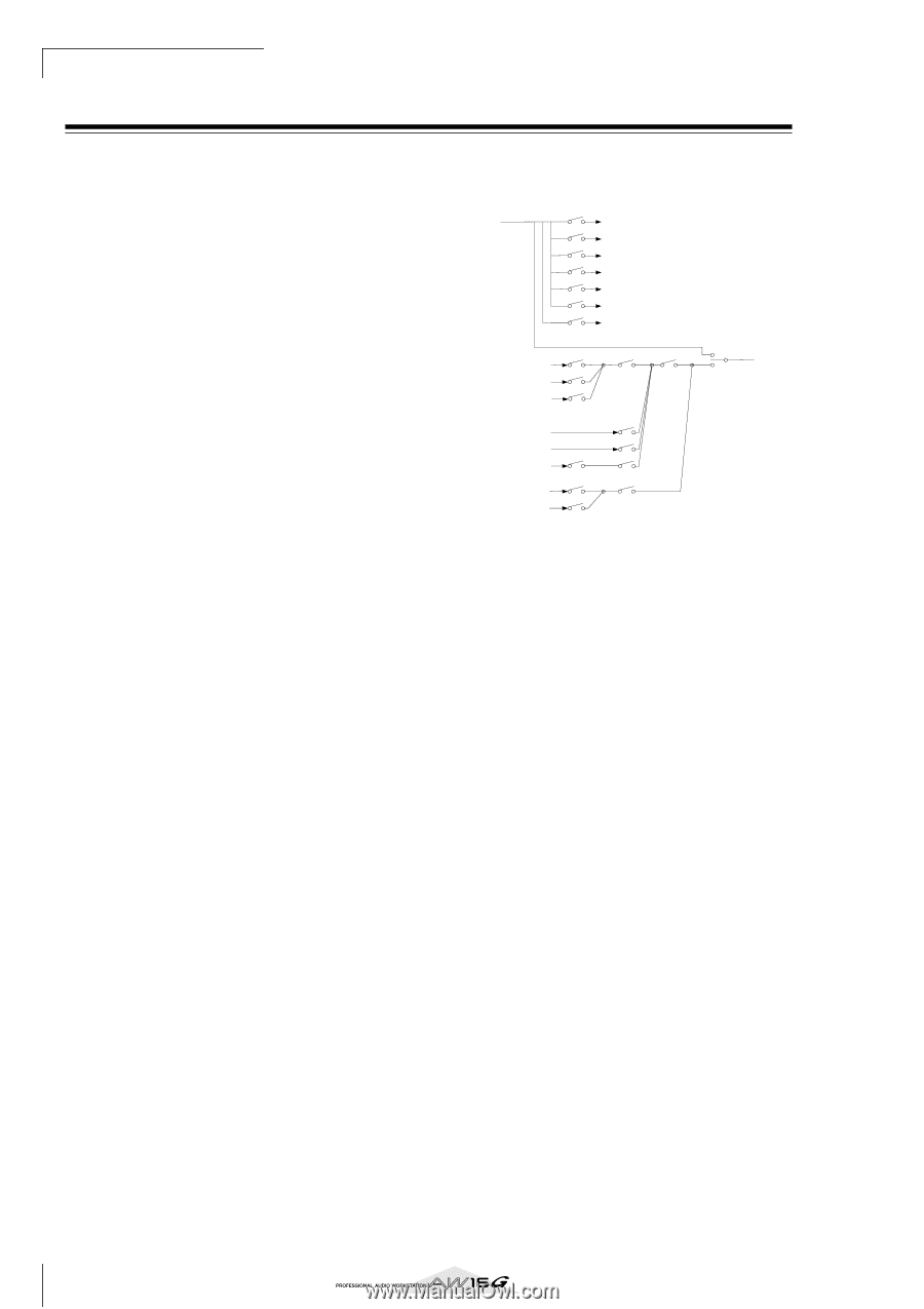
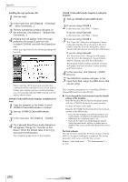
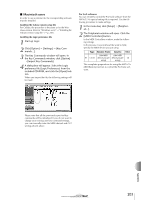
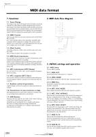
Appendix MIDI data format 1. Functions 1.1. Scene Change The settings of the [MIDI PROGRAM CHANGE TABLE] specify the scene that is recalled when a Program Change message is received. The settings of the [MIDI PROGRAM CHANGE TABLE] specify the program number that is transmitted when a scene is recalled. If more than one program number has been assigned to that scene memory number, the lowest-numbered program number will be transmitted. 1.2. MMC Control These messages allow basic recorder operations such as STOP/PLAY/ REC/LOCATE. If you select the MIDI SETUP menu item MMC MASTER, MMC commands will be transmitted according to the operation of the transport. If you select MMC SLAVE, the internal recorder will operate according to the received MMC commands. 1.3. Effect Control Depending on the type of effect, note-on/off messages can be used for control. These settings are made for the parameters of each effect. 1.4. MIDI Clock transmission If you set MIDI OUT to MIDI CLOCK, MIDI clock messages can be transmitted during playback or recording. In MIDI Clock transmission mode, Song Position Pointer and Start/ Stop/Continue commands will also be issued, and during playback or recording, MIDI Clock will be transmitted according to the MIDI Tempo Map. 1.5. MTC transmission (MTC Master) If you set MIDI OUT to MTC, MTC can be transmitted during playback or recording. 1.6. MTC reception (MTC Slave) If you set MTC MODE to SLAVE, the internal recorder will operate in synchronization with MTC messages received from the MIDI IN connector. 1.7. Realtime control of parameters Control changes can be used to send/receive internal parameters in realtime. 1.8. Transmission of scene memories or data The bulk dump function can be used to send data to another device, or copy settings from another device to the AW16G. 1.9. MIDI Remote The faders, SEL keys, and RTZ / FF / REW / STOP / PLAY / REC keys can be used to control an external MIDI device. In PRESET mode, operating the above controllers will transmit MIDI data according to the preset settings of the AW16G. In USER mode, operating the above controllers will transmit the MIDI data that you specify. 204 2. MIDI data flow diagram MIDI IN MTC SLAVE EFF MIDI PGM CHG CTRL CHG RX DISABLE MMC SLAVE LEARN MTC (MTC Slave) NOTE ON/OFF (Effect Control) PROGRAM CHANGE (Scene Recall) CONTROL CHANGE (Parameter Edit) BULK DUMP / BULK DUMP Request MMC (Transport Control) Channel Message / Exclusive Message (MIDI REMOTE Learn) PGM CHG PROGRAM CHANGE CTRL CHG CONTROL CHANGE TRANSMIT/REQUEST BULK DUMP / BULK DUMP Request MIDI OUT (THRU) SW1 MIDI OUT (MIDI) MIDI OUT SW2 REMOTE Transport SW3 REMOTE Fader/Sel MMC MASTER SW4 MMC MIDI OUT (MTC) SW4 MTC MIDI CLOCK MIDI OUT (CLK) SW1 REMOTE OFF SW2 REMOTE ON(Remote) SW3 REMOTE ON SW4 REMOTE OFF or REMOTE ON(Normal) 3. AW16G settings and operation 3.1. MIDI Setup Set basic MIDI operation. 3.1.1. MIDI OUT Specify the function of the MIDI OUT connector. 3.1.2. MMC MODE Select whether the AW16G will be the MMC MASTER or SLAVE. 3.1.3. MMC Dev. Specify the ID number that will be used when transmitting or receiving MMC commands. 3.1.4. MTC SYNC MODE Select whether the AW16G will be the MTC MASTER or SLAVE. 3.1.5. MTC SYNC AVERAGE When the AW16G is functioning as a MTC SLAVE, this setting specifies how it will follow the MTC data. Set this to 0 if the incoming MTC data has a highly accurate timing; set this to 1 or 2 if the timing of the incoming MTC data is not as accurate (such as when receiving MTC from a software sequencer). 3.1.6. MTC SYNC OFFSET When the AW16G is functioning as a MTC SLAVE, this setting adds an offset to the received MTC data. The received time code value shifted by this amount will correspond to the location indicated by the internal time code of the AW16G. 3.1.7. MIDI Tx Ch This sets the MIDI channel that will normally be used. However, transmission in response to a request will occur on the Receive Channel, in order to specify the device that transmitted the request. 3.1.8. MIDI Rx Ch This sets the MIDI channel that will be used for reception. If this is set to ALL, data of all MIDI channels will be receive d.
-
 1
1 -
2
-
3
-
4
-
5
-
6
-
7
-
8
-
9
-
10
-
11
-
12
-
13
-
14
-
15
-
16
-
17
-
18
-
19
-
20
-
21
-
22
-
23
-
24
-
25
-
26
-
27
-
28
-
29
-
30
-
31
-
32
-
33
-
34
-
35
-
36
-
37
-
38
-
39
-
40
-
41
-
42
-
43
-
44
-
45
-
46
-
47
-
48
-
49
-
50
-
51
-
52
-
53
-
54
-
55
-
56
-
57
-
58
-
59
-
60
-
61
-
62
-
63
-
64
-
65
-
66
-
67
-
68
-
69
-
70
-
71
-
72
-
73
-
74
-
75
-
76
-
77
-
78
-
79
-
80
-
81
-
82
-
83
-
84
-
85
-
86
-
87
-
88
-
89
-
90
-
91
-
92
-
93
-
94
-
95
-
96
-
97
-
98
-
99
-
100
-
101
-
102
-
103
-
104
-
105
-
106
-
107
-
108
-
109
-
110
-
111
-
112
-
113
-
114
-
115
-
116
-
117
-
118
-
119
-
120
-
121
-
122
-
123
-
124
-
125
-
126
-
127
-
128
-
129
-
130
-
131
-
132
-
133
-
134
-
135
-
136
-
137
-
138
-
139
-
140
-
141
-
142
-
143
-
144
-
145
-
146
-
147
-
148
-
149
-
150
-
151
-
152
-
153
-
154
-
155
-
156
-
157
-
158
-
159
-
160
-
161
-
162
-
163
-
164
-
165
-
166
-
167
-
168
-
169
-
170
-
171
-
172
-
173
-
174
-
175
-
176
-
177
-
178
-
179
-
180
-
181
-
182
-
183
-
184
-
185
-
186
-
187
-
188
-
189
-
190
-
191
-
192
-
193
-
194
-
195
-
196
-
197
-
198
-
 199
199 -
 200
200 -
 201
201 -
 202
202 -
 203
203 -
 204
204 -
 205
205 -
 206
206 -
 207
207 -
 208
208 -
 209
209 -
210
-
211
-
212
-
213
-
214
-
215
-
216
-
217
-
218
-
219
 |
 |