Cisco SA520-K9 Administration Guide - Page 16
Hardware Installation, STEP 1
 |
UPC - 882658266744
View all Cisco SA520-K9 manuals
Add to My Manuals
Save this manual to your list of manuals |
Page 16 highlights
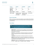
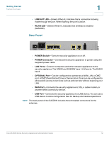
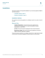
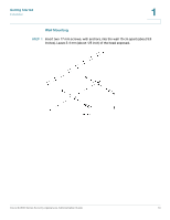
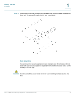
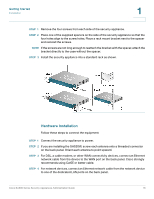
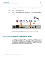
Getting Started Installation 1 STEP 1 Remove the four screws from each side of the security appliance. STEP 2 Place one of the supplied spacers on the side of the security appliance so that the four holes align to the screw holes. Place a rack mount bracket next to the spacer and reinstall the screws. NOTE If the screws are not long enough to reattach the bracket with the spacer, attach the bracket directly to the case without the spacer. STEP 3 Install the security appliance into a standard rack as shown. Hardware Installation Follow these steps to connect the equipment: STEP 1 Connect the security appliance to power. STEP 2 If you are installing the SA520W, screw each antenna onto a threaded connector on the back panel. Orient each antenna to point upward. STEP 3 For DSL, a cable modem, or other WAN connectivity devices, connect an Ethernet network cable from the device to the WAN port on the back panel. Cisco strongly recommends using Cat5E or better cable. STEP 4 For network devices, connect an Ethernet network cable from the network device to one of the dedicated LAN ports on the back panel. Cisco SA500 Series Security Appliances Administration Guide 16
-
 1
1 -
2
-
3
-
4
-
5
-
6
-
7
-
8
-
9
-
10
-
 11
11 -
 12
12 -
 13
13 -
 14
14 -
 15
15 -
 16
16 -
 17
17 -
 18
18 -
 19
19 -
 20
20 -
 21
21 -
22
-
23
-
24
-
25
-
26
-
27
-
28
-
29
-
30
-
31
-
32
-
33
-
34
-
35
-
36
-
37
-
38
-
39
-
40
-
41
-
42
-
43
-
44
-
45
-
46
-
47
-
48
-
49
-
50
-
51
-
52
-
53
-
54
-
55
-
56
-
57
-
58
-
59
-
60
-
61
-
62
-
63
-
64
-
65
-
66
-
67
-
68
-
69
-
70
-
71
-
72
-
73
-
74
-
75
-
76
-
77
-
78
-
79
-
80
-
81
-
82
-
83
-
84
-
85
-
86
-
87
-
88
-
89
-
90
-
91
-
92
-
93
-
94
-
95
-
96
-
97
-
98
-
99
-
100
-
101
-
102
-
103
-
104
-
105
-
106
-
107
-
108
-
109
-
110
-
111
-
112
-
113
-
114
-
115
-
116
-
117
-
118
-
119
-
120
-
121
-
122
-
123
-
124
-
125
-
126
-
127
-
128
-
129
-
130
-
131
-
132
-
133
-
134
-
135
-
136
-
137
-
138
-
139
-
140
-
141
-
142
-
143
-
144
-
145
-
146
-
147
-
148
-
149
-
150
-
151
-
152
-
153
-
154
-
155
-
156
-
157
-
158
-
159
-
160
-
161
-
162
-
163
-
164
-
165
-
166
-
167
-
168
-
169
-
170
-
171
-
172
-
173
-
174
-
175
-
176
-
177
-
178
-
179
-
180
-
181
-
182
-
183
-
184
-
185
-
186
-
187
-
188
-
189
-
190
-
191
-
192
-
193
-
194
-
195
-
196
-
197
-
198
-
199
-
200
-
201
-
202
-
203
-
204
-
205
-
206
-
207
-
208
-
209
-
210
-
211
-
212
-
213
-
214
-
215
-
216
-
217
-
218
-
219
-
220
-
221
-
222
-
223
-
224
-
225
-
226
-
227
-
228
-
229
-
230
-
231
-
232
-
233
-
234
-
235
-
236
-
237
-
238
-
239
-
240
 |
 |
