D-Link DGS-3200-10 Product Manual - Page 103
ISM VLAN Settings, Restrictions and Provisos - 28
 |
UPC - 790069306310
View all D-Link DGS-3200-10 manuals
Add to My Manuals
Save this manual to your list of manuals |
Page 103 highlights
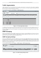
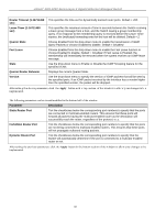
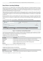
xStack® DGS-3200 Series Layer 2 Gigabit Ethernet Managed Switch ISM VLAN Settings In a switching environment, multiple VLANs may exist. Every time a multicast query passes through the Switch, the switch must forward separate different copies of the data to each VLAN on the system, which, in turn, increases data traffic and may clog up the traffic path. To lighten the traffic l oad, multicast VLANs may be incorporated. These multicast VLANs will allow the Switch to forward this multicast traffic as one copy to recipients of the multicast VLAN, instead of multiple copies. Regardless of other normal VLANs that are incorporated on t he Switch, users may add any ports to the multicast VLAN where they wish multicast traffic to be sent. Users are to set up a source port, where the multicast traffic is entering the switch, and then set the ports where the incoming multicast traffic is to be sent. The source port cannot be a recipient port and if configured to do so, will cause error messages to be produced by the switch. Once properly configured, the stream of multicast data will be relayed to the receiver ports in a much more timely and reliable fashion. Restrictions and Provisos The Multicast VLAN feature of this Switch does have some restrictions and limitations, such as: 1. Multicast VLANs can be implemented on edge and non-edge switches. 2. Member ports and source ports can be used in multiple ISM VLANs. But member ports and source ports cannot be the same port in a specific ISM VLAN. 3. The Multicast VLAN is exclusive with normal 802.1q VLANs, which means that VLAN IDs (VIDs) and VLAN Names of 802.1q VLANs and ISM VLANs cannot be the same. Once a VID or VLAN Name is chosen for any VLAN, it cannot be used for any other VLAN. 4. The normal display of configured VLANs will not display configured Multicast VLANs. 5. Once an ISM VLAN is enabled, the corresponding IGMP snooping state of this VLAN will also be enabled. Users cannot disable the IGMP feature for an enabled ISM VLAN. 6. One IP multicast address cannot be added to multiple ISM VLANs, yet multiple Ranges can be added to one ISM VLAN. Users can create and configure multicast VLANs for the Switch. To view the following window, click L2 Features > IGMP Snooping > ISM VLAN Settings: Figure 3 - 28. ISM VLAN Settings window The following parameters may be viewed or modified: Parameter Description ISM VLAN Global State Enable or disable the IGMP Snooping Multicast (ISM) VLAN Global State. Click Apply button to confirm the ISM VLAN Global State. VLAN Name Enter the name of the new Multicast VLAN to be created. This name can be up to 32 characters in length. This field will display the pre-created name of a Multicast VLAN in the Modify window. State Use the drop-down menu to enable or disable the selected Multicast VLAN. 90
-
 1
1 -
2
-
3
-
4
-
5
-
6
-
7
-
8
-
9
-
10
-
11
-
12
-
13
-
14
-
15
-
16
-
17
-
18
-
19
-
20
-
21
-
22
-
23
-
24
-
25
-
26
-
27
-
28
-
29
-
30
-
31
-
32
-
33
-
34
-
35
-
36
-
37
-
38
-
39
-
40
-
41
-
42
-
43
-
44
-
45
-
46
-
47
-
48
-
49
-
50
-
51
-
52
-
53
-
54
-
55
-
56
-
57
-
58
-
59
-
60
-
61
-
62
-
63
-
64
-
65
-
66
-
67
-
68
-
69
-
70
-
71
-
72
-
73
-
74
-
75
-
76
-
77
-
78
-
79
-
80
-
81
-
82
-
83
-
84
-
85
-
86
-
87
-
88
-
89
-
90
-
91
-
92
-
93
-
94
-
95
-
96
-
97
-
 98
98 -
 99
99 -
 100
100 -
 101
101 -
 102
102 -
 103
103 -
 104
104 -
 105
105 -
 106
106 -
 107
107 -
 108
108 -
109
-
110
-
111
-
112
-
113
-
114
-
115
-
116
-
117
-
118
-
119
-
120
-
121
-
122
-
123
-
124
-
125
-
126
-
127
-
128
-
129
-
130
-
131
-
132
-
133
-
134
-
135
-
136
-
137
-
138
-
139
-
140
-
141
-
142
-
143
-
144
-
145
-
146
-
147
-
148
-
149
-
150
-
151
-
152
-
153
-
154
-
155
-
156
-
157
-
158
-
159
-
160
-
161
-
162
-
163
-
164
-
165
-
166
-
167
-
168
-
169
-
170
-
171
-
172
-
173
-
174
-
175
-
176
-
177
-
178
-
179
-
180
-
181
-
182
-
183
-
184
-
185
-
186
-
187
-
188
-
189
-
190
-
191
-
192
-
193
-
194
-
195
-
196
-
197
-
198
-
199
-
200
-
201
-
202
-
203
-
204
-
205
-
206
-
207
-
208
-
209
-
210
-
211
-
212
-
213
-
214
-
215
-
216
-
217
-
218
-
219
-
220
-
221
-
222
-
223
-
224
-
225
-
226
-
227
-
228
-
229
-
230
-
231
-
232
-
233
-
234
-
235
-
236
-
237
-
238
-
239
-
240
-
241
-
242
-
243
-
244
-
245
-
246
-
247
-
248
-
249
-
250
-
251
-
252
-
253
-
254
-
255
-
256
-
257
-
258
-
259
-
260
-
261
-
262
-
263
-
264
-
265
-
266
-
267
-
268
-
269
-
270
-
271
-
272
-
273
-
274
-
275
-
276
-
277
-
278
-
279
-
280
-
281
-
282
-
283
-
284
-
285
-
286
-
287
-
288
-
289
-
290
-
291
-
292
-
293
-
294
-
295
-
296
-
297
-
298
-
299
-
300
-
301
-
302
 |
 |