D-Link DGS-3200-10 Product Manual - Page 23
Setting the Switch’s IP Address using the Console Interface, IPv6 Interface Settings - snmp
 |
UPC - 790069306310
View all D-Link DGS-3200-10 manuals
Add to My Manuals
Save this manual to your list of manuals |
Page 23 highlights
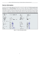
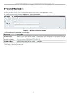
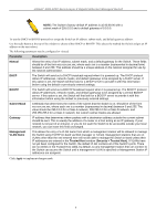
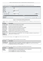
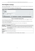
xStack® DGS-3200 Series Layer 2 Gigabit Ethernet Managed Switch Setting the Switch's IP Address using the Console Interface Each Switch must be assi gned its own IP Address, which is used for communication with an SNMP network manager or other TCP/IP application (for example BOOTP, TFTP). The Switch's default IP a ddress is 10.90.90.90. The default Switch IP address can be changed to meet the specification of your networking address scheme. The IP address for the Switch must be set before the Web-based manager can manage the switch. The Switch IP address can be automatically set using BOOTP or DHCP protocols, in which case the actual address assigned to the Switch must be known. The IP address may be set using the Command Line Interface (CLI) over the console serial port as follows: Starting at the command line prom pt, enter the c ommands config ipif Sy stem ipaddress xxx.xxx.xxx.xxx/ yyy.yyy.yyy.yyy. Where the x's represent the IP address t o be assigned to the IP interface nam ed System and the y's represent the corresponding subnet mask. Alternatively, the user ca n enter config i pif Sy stem ipa ddress xxx.xxx.xxx.xxx/z. Whe re the x's represent the IP address to be assigned to the IP interface named System and the z represents the corresponding number of subnets in CIDR notation. The IP interface named System on the Switch can be assigned an IP address and subnet mask, which can then be used to connect a management station to the Switch's Telnet or Web-based management agent. Successful entry of t he command will produce a "Success" message, indicating that the command execution was correctly. The user may now utilize this address to c onfigure or m anage the Switch through Tel net, the Command Line Interface (CLI) or the Web-based management (GUI). IPv6 Interface Settings Users can display the Switch's current IPv6 interface settings. To view the following window, click Configuration > IPv6 Interface Settings: Figure 2- 5. IPv6 Interface Settings window To configure IPv6 interface settings, enter an Interface Name, a VLAN Name, and make sure the Interface Admin. State is Enabled. Click the Create button. The new entry will appear in the Interface Table at the bottom of the window. 10
-
 1
1 -
2
-
3
-
4
-
5
-
6
-
7
-
8
-
9
-
10
-
11
-
12
-
13
-
14
-
15
-
16
-
17
-
 18
18 -
 19
19 -
 20
20 -
 21
21 -
 22
22 -
 23
23 -
 24
24 -
 25
25 -
 26
26 -
 27
27 -
 28
28 -
29
-
30
-
31
-
32
-
33
-
34
-
35
-
36
-
37
-
38
-
39
-
40
-
41
-
42
-
43
-
44
-
45
-
46
-
47
-
48
-
49
-
50
-
51
-
52
-
53
-
54
-
55
-
56
-
57
-
58
-
59
-
60
-
61
-
62
-
63
-
64
-
65
-
66
-
67
-
68
-
69
-
70
-
71
-
72
-
73
-
74
-
75
-
76
-
77
-
78
-
79
-
80
-
81
-
82
-
83
-
84
-
85
-
86
-
87
-
88
-
89
-
90
-
91
-
92
-
93
-
94
-
95
-
96
-
97
-
98
-
99
-
100
-
101
-
102
-
103
-
104
-
105
-
106
-
107
-
108
-
109
-
110
-
111
-
112
-
113
-
114
-
115
-
116
-
117
-
118
-
119
-
120
-
121
-
122
-
123
-
124
-
125
-
126
-
127
-
128
-
129
-
130
-
131
-
132
-
133
-
134
-
135
-
136
-
137
-
138
-
139
-
140
-
141
-
142
-
143
-
144
-
145
-
146
-
147
-
148
-
149
-
150
-
151
-
152
-
153
-
154
-
155
-
156
-
157
-
158
-
159
-
160
-
161
-
162
-
163
-
164
-
165
-
166
-
167
-
168
-
169
-
170
-
171
-
172
-
173
-
174
-
175
-
176
-
177
-
178
-
179
-
180
-
181
-
182
-
183
-
184
-
185
-
186
-
187
-
188
-
189
-
190
-
191
-
192
-
193
-
194
-
195
-
196
-
197
-
198
-
199
-
200
-
201
-
202
-
203
-
204
-
205
-
206
-
207
-
208
-
209
-
210
-
211
-
212
-
213
-
214
-
215
-
216
-
217
-
218
-
219
-
220
-
221
-
222
-
223
-
224
-
225
-
226
-
227
-
228
-
229
-
230
-
231
-
232
-
233
-
234
-
235
-
236
-
237
-
238
-
239
-
240
-
241
-
242
-
243
-
244
-
245
-
246
-
247
-
248
-
249
-
250
-
251
-
252
-
253
-
254
-
255
-
256
-
257
-
258
-
259
-
260
-
261
-
262
-
263
-
264
-
265
-
266
-
267
-
268
-
269
-
270
-
271
-
272
-
273
-
274
-
275
-
276
-
277
-
278
-
279
-
280
-
281
-
282
-
283
-
284
-
285
-
286
-
287
-
288
-
289
-
290
-
291
-
292
-
293
-
294
-
295
-
296
-
297
-
298
-
299
-
300
-
301
-
302
 |
 |