D-Link DGS-3200-10 Product Manual - Page 34
DHCP/BOOTP Relay, DHCP/BOOTP Relay Global Settings - 16 e
 |
UPC - 790069306310
View all D-Link DGS-3200-10 manuals
Add to My Manuals
Save this manual to your list of manuals |
Page 34 highlights
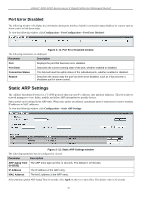
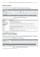
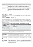
xStack® DGS-3200 Series Layer 2 Gigabit Ethernet Managed Switch Parameter Description System Severity Severity Level Choose how the alerts are used from the drop-down menu. Select Log to send the alert of the Severity Type configured to the Switch's log for analysis. Choose Trap to send it to an SNMP agent for analysis, or select All to send the chosen alert type to an SNMP agent and the Switch's log for analysis. Choose what level of alert will trigger sending the log entry or trap message as defined by the Severity Name. Select Critical to send only critical events to the Switch's log or SNMP agent. Choose Warning to send critical and warning events to the Switch's log or SNMP agent. Select Information to send informational, warning, and critical events to the Switch's log or SNMP agent. Click Apply to implement the new System Severity Settings. DHCP/BOOTP Relay The DHCP/BOOTP Rela y folder contains two windows: DHCP/BOOTP Rela y Global Se ttings and DHCP/BOOTP Rel ay Interface Settings. DHCP/BOOTP Relay Global Settings Users can enable and configure DHCP/BOOTP Relay Global Settings. The relay hops count limit allows the maximum number of hops (routers) that the DHCP/BOOTP messages can be relayed through to be set. If a packet's hop count is m ore than the hop count limit, the packet is dropped. The range is between 1 and 16 hops, with a default value of 4. The relay time threshold sets the minimum ti me (in seco nds) that th e Switch will wait before forwarding a BOOTREQUEST packet. If the value in the seconds field of the packet is less th an the relay time threshold, the p acket will be dropp ed. The ran ge is between 0 and 65,535 seconds, with a default value of 0 seconds. To view the following window, click Configuration > DHCP/BOOTP Relay > DHCP/BOOTP Relay Global Settings: Figure 2 - 18. DHCP/ BOOTP Relay Global Settings window The following parameters may be configured or viewed: Parameter Description DHCP/BOOTP Relay State This field can be toggled between Enabled and Disabled using the drop-down menu. It is used to enable or disable the DHCP/BOOTP Relay service on the Switch. The default is Disabled. DHCP/BOOTP Relay Hops Count Limit (116) This field allows an entry between 1 and 16 to define the maximum number of router hops DHCP/BOOTP messages can be forwarded. The default hop count is 4. DHCP/BOOTP Relay Time Threshold (065535) Allows an entry between 0 and 65535 seconds, and defines the maximum time limit for routing a DHCP/BOOTP packet. If a value of 0 is entered, the Switch will not process the value in the seconds field of the BOOTP or DHCP packet. If a non-zero value is entered, the Switch will use that value, along with the hop count to determine whether to forward a given BOOTP or DHCP packet. 21
-
 1
1 -
2
-
3
-
4
-
5
-
6
-
7
-
8
-
9
-
10
-
11
-
12
-
13
-
14
-
15
-
16
-
17
-
18
-
19
-
20
-
21
-
22
-
23
-
24
-
25
-
26
-
27
-
28
-
 29
29 -
 30
30 -
 31
31 -
 32
32 -
 33
33 -
 34
34 -
 35
35 -
 36
36 -
 37
37 -
 38
38 -
 39
39 -
40
-
41
-
42
-
43
-
44
-
45
-
46
-
47
-
48
-
49
-
50
-
51
-
52
-
53
-
54
-
55
-
56
-
57
-
58
-
59
-
60
-
61
-
62
-
63
-
64
-
65
-
66
-
67
-
68
-
69
-
70
-
71
-
72
-
73
-
74
-
75
-
76
-
77
-
78
-
79
-
80
-
81
-
82
-
83
-
84
-
85
-
86
-
87
-
88
-
89
-
90
-
91
-
92
-
93
-
94
-
95
-
96
-
97
-
98
-
99
-
100
-
101
-
102
-
103
-
104
-
105
-
106
-
107
-
108
-
109
-
110
-
111
-
112
-
113
-
114
-
115
-
116
-
117
-
118
-
119
-
120
-
121
-
122
-
123
-
124
-
125
-
126
-
127
-
128
-
129
-
130
-
131
-
132
-
133
-
134
-
135
-
136
-
137
-
138
-
139
-
140
-
141
-
142
-
143
-
144
-
145
-
146
-
147
-
148
-
149
-
150
-
151
-
152
-
153
-
154
-
155
-
156
-
157
-
158
-
159
-
160
-
161
-
162
-
163
-
164
-
165
-
166
-
167
-
168
-
169
-
170
-
171
-
172
-
173
-
174
-
175
-
176
-
177
-
178
-
179
-
180
-
181
-
182
-
183
-
184
-
185
-
186
-
187
-
188
-
189
-
190
-
191
-
192
-
193
-
194
-
195
-
196
-
197
-
198
-
199
-
200
-
201
-
202
-
203
-
204
-
205
-
206
-
207
-
208
-
209
-
210
-
211
-
212
-
213
-
214
-
215
-
216
-
217
-
218
-
219
-
220
-
221
-
222
-
223
-
224
-
225
-
226
-
227
-
228
-
229
-
230
-
231
-
232
-
233
-
234
-
235
-
236
-
237
-
238
-
239
-
240
-
241
-
242
-
243
-
244
-
245
-
246
-
247
-
248
-
249
-
250
-
251
-
252
-
253
-
254
-
255
-
256
-
257
-
258
-
259
-
260
-
261
-
262
-
263
-
264
-
265
-
266
-
267
-
268
-
269
-
270
-
271
-
272
-
273
-
274
-
275
-
276
-
277
-
278
-
279
-
280
-
281
-
282
-
283
-
284
-
285
-
286
-
287
-
288
-
289
-
290
-
291
-
292
-
293
-
294
-
295
-
296
-
297
-
298
-
299
-
300
-
301
-
302
 |
 |
