D-Link DGS-3200-10 Product Manual - Page 109
Max Multicast Group Settings, MLD Snooping Settings
 |
UPC - 790069306310
View all D-Link DGS-3200-10 manuals
Add to My Manuals
Save this manual to your list of manuals |
Page 109 highlights
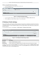
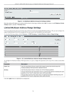
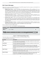
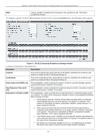
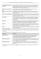
xStack® DGS-3200 Series Layer 2 Gigabit Ethernet Managed Switch To configure the Multicast Address Filtering function on a port for a specific Profile, configure the parameters in the center of the window as described below: Parameter Description From / To Profile ID Access Use the drop-down menus to specify the range of ports that need to have the multicast address filtering function added/removed. Use the drop-down menu to choose the Profile ID that needs to be added to or removed from the specified range of ports. Use the drop-down menu to choose one of the following options: Choose Permit from the drop-down menu to specify that packets matching the addresses specified in the profile will be permitted. Choose Deny from the drop-down menu to specify that packets matching the addresses specified in the profile will be denied. Click the Add button to add the new Limited Multicast Address Range Setting. Click the Delete button to delete an existing Limited Multicast Address Range Setting. Max Multicast Group Settings Users can configure the ports on the switch that will be a part of the maximum filter group, up to a maximum of 256. To view the following window, click L2 Features > IGMP Snooping > Max Multicast Group Settings: Figure 3- 36. Max Multicast Group Settings window To add a Maximum Multicast Group range, enter the appropriate information and then click Apply. MLD Snooping Settings Multicast Listener Discovery (MLD) Snooping is an IPv6 function used similarly to IGMP snooping in IPv4. It is used to discover ports on a VLAN that are requesting multicast data. Instead of flooding all ports on a selected VLAN with multicast traffic, MLD snooping will only forward multicast data to ports that wish to receive this data through the use of queries and reports produced by the requesting ports and the source of the multicast traffic. MLD snooping is accomplished through the examination of the layer 3 part of an MLD control packet transferred between end nodes and a MLD router. When the Switch discovers that this route is requesting multicast traffic, it adds the port directly attached to it i nto th e co rrect IPv6 m ulticast tab le, and begins th e pro cess of forwarding m ulticast traffi c t o that port. This ent ry i n th e multicast ro uting tab le reco rds th e port, t he VLAN ID, and t he ass ociated m ulticast IPv6 m ulticast gr oup a ddress, an d t hen considers this port to be an active listening port. The active listening ports are the only ones to receive multicast group data. 96
-
 1
1 -
2
-
3
-
4
-
5
-
6
-
7
-
8
-
9
-
10
-
11
-
12
-
13
-
14
-
15
-
16
-
17
-
18
-
19
-
20
-
21
-
22
-
23
-
24
-
25
-
26
-
27
-
28
-
29
-
30
-
31
-
32
-
33
-
34
-
35
-
36
-
37
-
38
-
39
-
40
-
41
-
42
-
43
-
44
-
45
-
46
-
47
-
48
-
49
-
50
-
51
-
52
-
53
-
54
-
55
-
56
-
57
-
58
-
59
-
60
-
61
-
62
-
63
-
64
-
65
-
66
-
67
-
68
-
69
-
70
-
71
-
72
-
73
-
74
-
75
-
76
-
77
-
78
-
79
-
80
-
81
-
82
-
83
-
84
-
85
-
86
-
87
-
88
-
89
-
90
-
91
-
92
-
93
-
94
-
95
-
96
-
97
-
98
-
99
-
100
-
101
-
102
-
103
-
 104
104 -
 105
105 -
 106
106 -
 107
107 -
 108
108 -
 109
109 -
 110
110 -
 111
111 -
 112
112 -
 113
113 -
 114
114 -
115
-
116
-
117
-
118
-
119
-
120
-
121
-
122
-
123
-
124
-
125
-
126
-
127
-
128
-
129
-
130
-
131
-
132
-
133
-
134
-
135
-
136
-
137
-
138
-
139
-
140
-
141
-
142
-
143
-
144
-
145
-
146
-
147
-
148
-
149
-
150
-
151
-
152
-
153
-
154
-
155
-
156
-
157
-
158
-
159
-
160
-
161
-
162
-
163
-
164
-
165
-
166
-
167
-
168
-
169
-
170
-
171
-
172
-
173
-
174
-
175
-
176
-
177
-
178
-
179
-
180
-
181
-
182
-
183
-
184
-
185
-
186
-
187
-
188
-
189
-
190
-
191
-
192
-
193
-
194
-
195
-
196
-
197
-
198
-
199
-
200
-
201
-
202
-
203
-
204
-
205
-
206
-
207
-
208
-
209
-
210
-
211
-
212
-
213
-
214
-
215
-
216
-
217
-
218
-
219
-
220
-
221
-
222
-
223
-
224
-
225
-
226
-
227
-
228
-
229
-
230
-
231
-
232
-
233
-
234
-
235
-
236
-
237
-
238
-
239
-
240
-
241
-
242
-
243
-
244
-
245
-
246
-
247
-
248
-
249
-
250
-
251
-
252
-
253
-
254
-
255
-
256
-
257
-
258
-
259
-
260
-
261
-
262
-
263
-
264
-
265
-
266
-
267
-
268
-
269
-
270
-
271
-
272
-
273
-
274
-
275
-
276
-
277
-
278
-
279
-
280
-
281
-
282
-
283
-
284
-
285
-
286
-
287
-
288
-
289
-
290
-
291
-
292
-
293
-
294
-
295
-
296
-
297
-
298
-
299
-
300
-
301
-
302
 |
 |
