D-Link DGS-3200-10 Product Manual - Page 177
MAC Local Settings, Web-based Access Control (WAC) - d link default ip
 |
UPC - 790069306310
View all D-Link DGS-3200-10 manuals
Add to My Manuals
Save this manual to your list of manuals |
Page 177 highlights
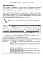
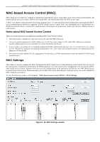
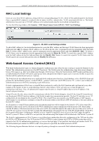
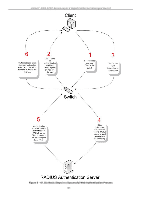
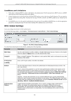
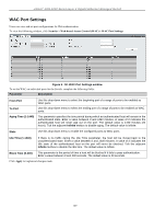
xStack® DGS-3200 Series Layer 2 Gigabit Ethernet Managed Switch MAC Local Settings Users can set a list of M AC addresses, along with their corresponding target VLAN, which will be authenticated for the Switch. Once a queried MAC a ddress is m atched in this wi ndow, it will be placed in the VLAN associated with it he re. The Switch administrator may enter up to 128 MAC addresses to be authenticated using the local method configured here. To view the following window, click Security > MAC-based Access Control (MAC)> MAC Local Settings: Figure 5 - 46. MAC Local Settings window To add a MAC address to t he local aut hentication list, en ter the MAC address and the target VLAN Nam e into their appropriate fields and click Add. To change a M AC address or a VL AN in the list, enter its parameters into the appropriate fields and click Edit. To d elete a MAC address en try, en ter its parameters in to th e appro priate field s and click Delete By MAC. To d elete a VLAN Name, enter its parameters into the appropriate fields and click Delete By VLAN. To search for a specific MAC Address, enter the MAC address in the first field and then click the Find By MAC button. To search for a specific VLAN Name, enter the VLAN name in the second field and then click the Find By VLAN button. Web-based Access Control (WAC) Web-based Authentication Login is a feature designed to authenticate a user when the user is trying t o access the Internet via the Switch. The a uthentication process use s t he HTT P p rotocol. T he Switch en ters th e au thenticating stage whe n us ers attem pt to browse Web pages (e.g., http://www.dlink.com) through a Web browser. When the Switch detects HTTP packets and this port is un-authenticated, the Switch will launch a pop-up user name and password window to query users. Users are not able to access the Internet until the authentication process is passed. The Switch can be the authentication server itself and do the authentication based on a local database, or be a RADIUS client and perform th e au thentication process via the RADIUS protocol with a rem ote RADIUS server. Th e clien t user in itiates th e authentication process of WAC by attempting to gain Web access. D-Link's implementation of WAC uses a virtual IP that is exclusively used by the WAC function and is not known by any other modules of the Switch. In fact, to avoid affecting a Switch's other features, WAC will only use a virtual IP address to communicate with hosts. Thus, all authentication requests must be sent to a virtual IP address but not to the IP address of the Switch's physical interface. Virtual IP works like this, when a host PC communicates with the WAC Switch through a virtual IP, the virtual IP is transformed into the physical IPIF (IP interface) address of the Switch to make the communication possible. The host PC and other servers' IP configurations do not depend on the virtual IP of WAC. The virtual IP does not respond to any ICMP packets or ARP requests, which means it is not allowed to configure a virtual IP on the same subnet as the Switch's IPIF (IP interface) or the same subnet as the host PCs' subnet. As all packets to a virtual IP from authenticated and authenticating hosts will be trapped to the Switch's CPU, if the virtual IP is the same as other servers or PCs, the hosts on the WAC-enabled ports cannot communicate with the server or PC which really own the IP address. If the hosts need to access the server or PC, the virtual IP cannot be the same as the one of the server or PC. If a host PC uses a proxy to access the Web, to make the authentication work properly the user of the PC should add the virtual IP to the exception of the proxy configuration. Whether or not a virtual IP is specified, users can access the WAC pages through the Switch's system IP. When a virtual IP is not specified, the authenticating Web request will be redirected to the Switch's system IP. The Switch's implementation of WAC features a user-defined port number that allows the configuration of the TCP port for either the HTTP or HTTPS protocols. This TCP port for HTTP or HTTPS is used to identify the HTTP or HTTPS packets that will be trapped to the CPU for authentication processing, or to access the login page. If not specified, the default port number for HTTP is 80 and the default port number for HTTPS is 443. If no protocol is specified, the default protocol is HTTP. The following diagram illustrates the basic six steps all parties go through in a successful Web Authentication process: 164
-
 1
1 -
2
-
3
-
4
-
5
-
6
-
7
-
8
-
9
-
10
-
11
-
12
-
13
-
14
-
15
-
16
-
17
-
18
-
19
-
20
-
21
-
22
-
23
-
24
-
25
-
26
-
27
-
28
-
29
-
30
-
31
-
32
-
33
-
34
-
35
-
36
-
37
-
38
-
39
-
40
-
41
-
42
-
43
-
44
-
45
-
46
-
47
-
48
-
49
-
50
-
51
-
52
-
53
-
54
-
55
-
56
-
57
-
58
-
59
-
60
-
61
-
62
-
63
-
64
-
65
-
66
-
67
-
68
-
69
-
70
-
71
-
72
-
73
-
74
-
75
-
76
-
77
-
78
-
79
-
80
-
81
-
82
-
83
-
84
-
85
-
86
-
87
-
88
-
89
-
90
-
91
-
92
-
93
-
94
-
95
-
96
-
97
-
98
-
99
-
100
-
101
-
102
-
103
-
104
-
105
-
106
-
107
-
108
-
109
-
110
-
111
-
112
-
113
-
114
-
115
-
116
-
117
-
118
-
119
-
120
-
121
-
122
-
123
-
124
-
125
-
126
-
127
-
128
-
129
-
130
-
131
-
132
-
133
-
134
-
135
-
136
-
137
-
138
-
139
-
140
-
141
-
142
-
143
-
144
-
145
-
146
-
147
-
148
-
149
-
150
-
151
-
152
-
153
-
154
-
155
-
156
-
157
-
158
-
159
-
160
-
161
-
162
-
163
-
164
-
165
-
166
-
167
-
168
-
169
-
170
-
171
-
 172
172 -
 173
173 -
 174
174 -
 175
175 -
 176
176 -
 177
177 -
 178
178 -
 179
179 -
 180
180 -
 181
181 -
 182
182 -
183
-
184
-
185
-
186
-
187
-
188
-
189
-
190
-
191
-
192
-
193
-
194
-
195
-
196
-
197
-
198
-
199
-
200
-
201
-
202
-
203
-
204
-
205
-
206
-
207
-
208
-
209
-
210
-
211
-
212
-
213
-
214
-
215
-
216
-
217
-
218
-
219
-
220
-
221
-
222
-
223
-
224
-
225
-
226
-
227
-
228
-
229
-
230
-
231
-
232
-
233
-
234
-
235
-
236
-
237
-
238
-
239
-
240
-
241
-
242
-
243
-
244
-
245
-
246
-
247
-
248
-
249
-
250
-
251
-
252
-
253
-
254
-
255
-
256
-
257
-
258
-
259
-
260
-
261
-
262
-
263
-
264
-
265
-
266
-
267
-
268
-
269
-
270
-
271
-
272
-
273
-
274
-
275
-
276
-
277
-
278
-
279
-
280
-
281
-
282
-
283
-
284
-
285
-
286
-
287
-
288
-
289
-
290
-
291
-
292
-
293
-
294
-
295
-
296
-
297
-
298
-
299
-
300
-
301
-
302
 |
 |