D-Link DGS-3200-10 Product Manual - Page 64
Single IP Settings window for Commander Enabled - d link firmware
 |
UPC - 790069306310
View all D-Link DGS-3200-10 manuals
Add to My Manuals
Save this manual to your list of manuals |
Page 64 highlights
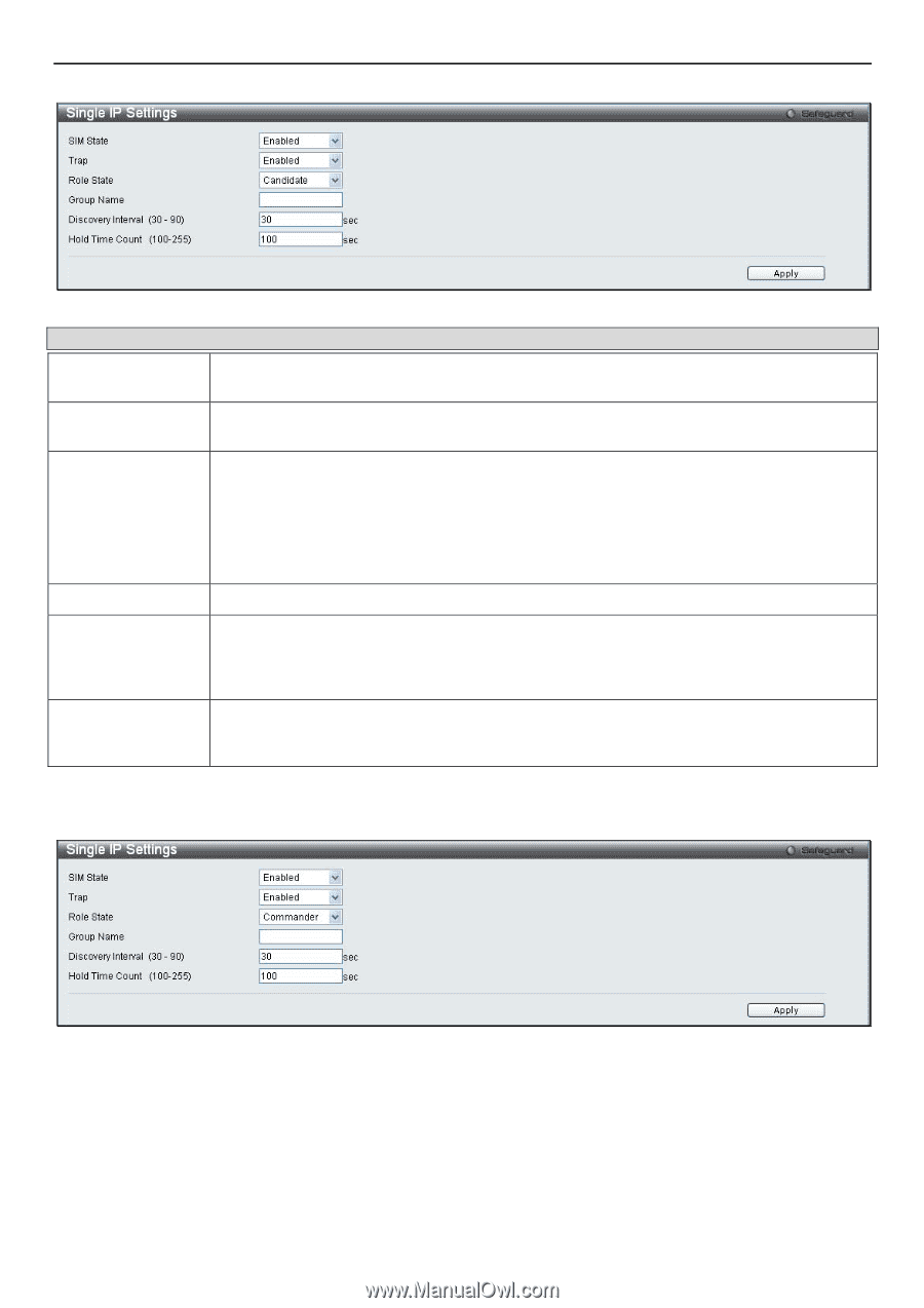
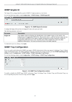
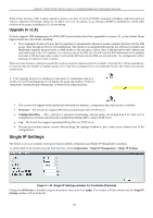
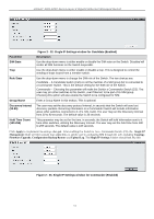
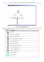
xStack® DGS-3200 Series Layer 2 Gigabit Ethernet Managed Switch Parameter SIM State Trap Role State Group Name Discovery Interval (30-90) Hold Time Count (100-255) Figure 2 - 52. Single IP Settings window for Candidate (Enabled) Description Use the drop-down menu to either enable or disable the SIM state on the Switch. Disabled will render all SIM functions on the Switch inoperable. Use the drop-down menu to either enable or disable a trap. This is designed to control the sending of traps issued from a member switch. Use the drop-down menu to change the SIM role of the Switch. The two choices are: Candidate - A Candidate Switch (CaS) is not the member of a SIM group but is connected to a Commander Switch. This is the default setting for the SIM role of the Switch. Commander - Choosing this parameter will make the Switch a Commander Switch (CS). The user may join other switches to this Switch, over Ethernet, to be part of its SIM group. Choosing this option will also enable the Switch to be configured for SIM. Enter a Group Name in this textbox. This is optional. The user may set the discovery protocol interval, in seconds that the Switch will send out discovery packets. Returning information to a Commander Switch will include information about other switches connected to it. (Ex. MS, CaS). The user may set the Discovery Interval from 30 to 90 seconds. The default value is 30 seconds. This parameter may be set for the time, in seconds; the Switch will hold information sent to it from other switches, utilizing the Discovery Interval. The user may set the hold time from 100 to 255 seconds. The default value is 100 seconds. Click Apply to im plement t he settin gs chan ged. After en abling th e Switch to be a Commander Switch (CS), the Single I P Management folder will th en contain four added links to aid the user in configuring SIM th rough the web, including Topology, Firmware Upgrade, Configuration Backup/Restore and Upload Log. The Single IP Settings window should look like this: Figure 2 - 53. Single IP Settings window for Commander (Enabled) 51
-
 1
1 -
2
-
3
-
4
-
5
-
6
-
7
-
8
-
9
-
10
-
11
-
12
-
13
-
14
-
15
-
16
-
17
-
18
-
19
-
20
-
21
-
22
-
23
-
24
-
25
-
26
-
27
-
28
-
29
-
30
-
31
-
32
-
33
-
34
-
35
-
36
-
37
-
38
-
39
-
40
-
41
-
42
-
43
-
44
-
45
-
46
-
47
-
48
-
49
-
50
-
51
-
52
-
53
-
54
-
55
-
56
-
57
-
58
-
 59
59 -
 60
60 -
 61
61 -
 62
62 -
 63
63 -
 64
64 -
 65
65 -
 66
66 -
 67
67 -
 68
68 -
 69
69 -
70
-
71
-
72
-
73
-
74
-
75
-
76
-
77
-
78
-
79
-
80
-
81
-
82
-
83
-
84
-
85
-
86
-
87
-
88
-
89
-
90
-
91
-
92
-
93
-
94
-
95
-
96
-
97
-
98
-
99
-
100
-
101
-
102
-
103
-
104
-
105
-
106
-
107
-
108
-
109
-
110
-
111
-
112
-
113
-
114
-
115
-
116
-
117
-
118
-
119
-
120
-
121
-
122
-
123
-
124
-
125
-
126
-
127
-
128
-
129
-
130
-
131
-
132
-
133
-
134
-
135
-
136
-
137
-
138
-
139
-
140
-
141
-
142
-
143
-
144
-
145
-
146
-
147
-
148
-
149
-
150
-
151
-
152
-
153
-
154
-
155
-
156
-
157
-
158
-
159
-
160
-
161
-
162
-
163
-
164
-
165
-
166
-
167
-
168
-
169
-
170
-
171
-
172
-
173
-
174
-
175
-
176
-
177
-
178
-
179
-
180
-
181
-
182
-
183
-
184
-
185
-
186
-
187
-
188
-
189
-
190
-
191
-
192
-
193
-
194
-
195
-
196
-
197
-
198
-
199
-
200
-
201
-
202
-
203
-
204
-
205
-
206
-
207
-
208
-
209
-
210
-
211
-
212
-
213
-
214
-
215
-
216
-
217
-
218
-
219
-
220
-
221
-
222
-
223
-
224
-
225
-
226
-
227
-
228
-
229
-
230
-
231
-
232
-
233
-
234
-
235
-
236
-
237
-
238
-
239
-
240
-
241
-
242
-
243
-
244
-
245
-
246
-
247
-
248
-
249
-
250
-
251
-
252
-
253
-
254
-
255
-
256
-
257
-
258
-
259
-
260
-
261
-
262
-
263
-
264
-
265
-
266
-
267
-
268
-
269
-
270
-
271
-
272
-
273
-
274
-
275
-
276
-
277
-
278
-
279
-
280
-
281
-
282
-
283
-
284
-
285
-
286
-
287
-
288
-
289
-
290
-
291
-
292
-
293
-
294
-
295
-
296
-
297
-
298
-
299
-
300
-
301
-
302
 |
 |