D-Link DGS-3200-10 Product Manual - Page 275
Table 6., Chunk and Packet Offset, A Completed ARP Packet Contained in an Ethernet Frame
 |
UPC - 790069306310
View all D-Link DGS-3200-10 manuals
Add to My Manuals
Save this manual to your list of manuals |
Page 275 highlights
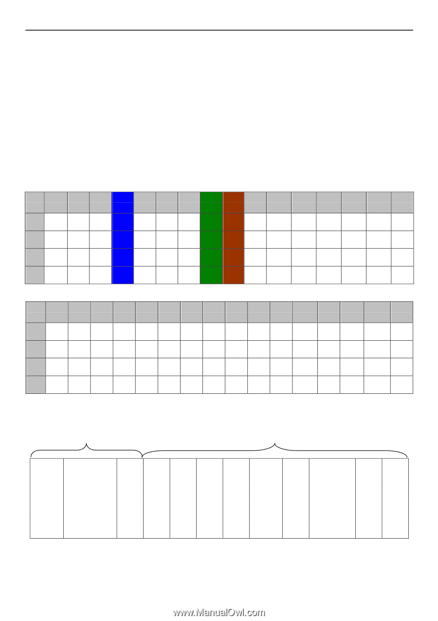
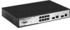
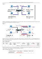
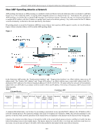
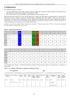
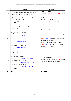
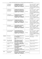
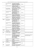
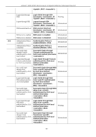
xStack® DGS-3200 Series Layer 2 Gigabit Ethernet Managed Switch Configuration The configuration logic is as follows: 1. Only if the ARP matches Source MAC address in Ethernet, Sender MAC address and Sender IP address in ARP protocol can pass through the switch. (In this example, it is the gateway's ARP.) 2. The switch will deny all other ARP packets which claim they are from the gateway's IP. The design of Packet Content ACL on the Switch enables users to inspect any offset chunk. An offset chunk is a 4-byte block in a HEX fo rmat, wh ich is utilized to m atch t he ind ividual field in an Et hernet frame. Each profile is allowed to con tain up to a maximum of f our offset ch unks. Furthermore, only o ne single p rofile of Pac ket C ontent AC L ca n be s upported p er s witch. In other words, up to 16 bytes of total offset chunks can be applied to each profile and a switch. Therefore, a careful consideration is needed for planning and configuration of the valuable offset chunks. In Table 6, you will no tice that the Offset_Chunk0 starts from the 127th byte and ends at the 128th byte. It also can be found that the offset chunk is scratched from 1 but not zero. Table 6. Chunk and Packet Offset Offset Offset Offset Offset Offset Offset Offset Offset Offset Offset Offset Offset Offset Offset Offset Offset Offset Chunk Chunk0 Chunk1 Chunk2 Chunk3 Chunk4 Chunk5 Chunk6 Chunk7 Chunk8 Chunk9 Chunk10 Chunk11 Chunk12 Chunk13 Chunk14 Chunk15 Byte 127 3 7 11 15 19 23 27 31 35 39 43 47 51 55 59 Byte 128 4 8 12 16 20 24 28 32 36 40 44 48 52 56 60 Byte 1 5 9 13 17 21 25 29 33 37 41 45 49 53 57 61 Byte 2 6 10 14 18 22 26 30 34 38 42 46 50 54 58 62 Offset Offset Offset Offset Offset Offset Offset Offset Offset Offset Offset Offset Offset Offset Offset Offset Offset Chunk Chunk16 Chunk17 Chunk18 Chunk19 Chunk20 Chunk21 Chunk22 Chunk23 Chunk24 Chunk25 Chunk26 Chunk27 Chunk28 Chunk29 Chunk30 Chunk31 Byte 63 67 71 75 79 83 87 91 95 99 103 107 111 115 119 123 Byte 64 68 72 76 80 84 88 92 96 100 104 108 112 116 120 124 Byte 65 69 73 77 81 85 89 93 97 101 105 109 113 117 121 125 Byte 66 70 74 78 82 86 90 94 98 102 106 110 114 118 122 126 The following t able i ndicates a c ompleted AR P packet c ontained in Et hernet fram e whic h is t he pattern for the calculation of packet offset. Table 7. A Completed ARP Packet Contained in an Ethernet Frame Ethernet Header ARP Destination Address Source Address Ethernet Type H/W Type Protocol H/W Protocol Operation Sender Sender Protocol Target Target Type Address Address H/W Address H/W Protocol Length Length Address Address Address (6-byte) (6-byte) (2-byte) (2-byte) (2-byte) (1-byte) (1-byte) (2-byte) (6-byte) (4-byte) (6-byte) (4-byte) 01 02 03 04 05 06 0806 0a5a5a5a (10.90.90.90) 262
-
 1
1 -
2
-
3
-
4
-
5
-
6
-
7
-
8
-
9
-
10
-
11
-
12
-
13
-
14
-
15
-
16
-
17
-
18
-
19
-
20
-
21
-
22
-
23
-
24
-
25
-
26
-
27
-
28
-
29
-
30
-
31
-
32
-
33
-
34
-
35
-
36
-
37
-
38
-
39
-
40
-
41
-
42
-
43
-
44
-
45
-
46
-
47
-
48
-
49
-
50
-
51
-
52
-
53
-
54
-
55
-
56
-
57
-
58
-
59
-
60
-
61
-
62
-
63
-
64
-
65
-
66
-
67
-
68
-
69
-
70
-
71
-
72
-
73
-
74
-
75
-
76
-
77
-
78
-
79
-
80
-
81
-
82
-
83
-
84
-
85
-
86
-
87
-
88
-
89
-
90
-
91
-
92
-
93
-
94
-
95
-
96
-
97
-
98
-
99
-
100
-
101
-
102
-
103
-
104
-
105
-
106
-
107
-
108
-
109
-
110
-
111
-
112
-
113
-
114
-
115
-
116
-
117
-
118
-
119
-
120
-
121
-
122
-
123
-
124
-
125
-
126
-
127
-
128
-
129
-
130
-
131
-
132
-
133
-
134
-
135
-
136
-
137
-
138
-
139
-
140
-
141
-
142
-
143
-
144
-
145
-
146
-
147
-
148
-
149
-
150
-
151
-
152
-
153
-
154
-
155
-
156
-
157
-
158
-
159
-
160
-
161
-
162
-
163
-
164
-
165
-
166
-
167
-
168
-
169
-
170
-
171
-
172
-
173
-
174
-
175
-
176
-
177
-
178
-
179
-
180
-
181
-
182
-
183
-
184
-
185
-
186
-
187
-
188
-
189
-
190
-
191
-
192
-
193
-
194
-
195
-
196
-
197
-
198
-
199
-
200
-
201
-
202
-
203
-
204
-
205
-
206
-
207
-
208
-
209
-
210
-
211
-
212
-
213
-
214
-
215
-
216
-
217
-
218
-
219
-
220
-
221
-
222
-
223
-
224
-
225
-
226
-
227
-
228
-
229
-
230
-
231
-
232
-
233
-
234
-
235
-
236
-
237
-
238
-
239
-
240
-
241
-
242
-
243
-
244
-
245
-
246
-
247
-
248
-
249
-
250
-
251
-
252
-
253
-
254
-
255
-
256
-
257
-
258
-
259
-
260
-
261
-
262
-
263
-
264
-
265
-
266
-
267
-
268
-
269
-
 270
270 -
 271
271 -
 272
272 -
 273
273 -
 274
274 -
 275
275 -
 276
276 -
 277
277 -
 278
278 -
 279
279 -
 280
280 -
281
-
282
-
283
-
284
-
285
-
286
-
287
-
288
-
289
-
290
-
291
-
292
-
293
-
294
-
295
-
296
-
297
-
298
-
299
-
300
-
301
-
302
 |
 |