D-Link DGS-3200-10 Product Manual - Page 270
Appendix A - Mitigating ARP Spoofing Attacks, Using Packet Content ACL
 |
UPC - 790069306310
View all D-Link DGS-3200-10 manuals
Add to My Manuals
Save this manual to your list of manuals |
Page 270 highlights
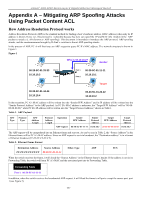
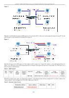
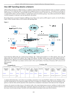
xStack® DGS-3200 Series Layer 2 Gigabit Ethernet Managed Switch Appendix A - Mitigating ARP Spoofing Attacks Using Packet Content ACL How Address Resolution Protocol works Address Resolution Protocol (ARP) is the standard method for finding a host's hardware address (MAC address) when only its IP address is known. Howe ver, this prot ocol is vulnerable because hac kers can spoof the IP and MAC info rmation in the ARP packets t o attack a L AN (known as ARP spoofing). This doc ument i s int ended t o i ntroduce t he ARP pr otocol, ARP sp oofing attacks, and the countermeasures brought by D-Link's switches to thwart ARP spoofing attacks. In the process of ARP, PC A will first issu e an ARP request to query PC B's MAC address. Th e network structure is sho wn in Figure 1. Figure 1 C Who is 10.10.10.2? A Sender 00-20-5C-01-33-33 10.10.10.3 D Port 3 Port 4 Port 1 Port 2 00-20-5C-01-11-11 10.10.10.1 B Target 00-20-5C-01-44-44 10.10.10.4 00-20-5C-01-22-22 10.10.10.2 In the meantime, PC A's M AC address will be written into the "Sender H/W Address" and its IP address will be written into the "Sender Protocol Address" in the ARP payload. As PC B's MAC address is unknown, the "Target H/W Address" will be "00-0000-00-00-00," while PC B's IP address will be written into the "Target Protocol Address," shown in Table1. Table 1. ARP Payload H/W Protocol Type Type H/W Address Length Protocol Address Length Operation ARP request Sender H/W Address 00-20-5C-01-11-11 Sender Protocol Address 10.10.10.1 Target H/W Address 00-00-00-00-00-00 Target Protocol Address 10.10.10.2 The ARP request will be encapsulated into an Ethernet frame and sent out. As can be seen in Table 2, the "Source Address" in the Ethernet frame will be PC A's MAC add ress. Since an ARP request is sent via broadcast, the "Destination address" is in a format of Ethernet broadcast (FF-FF-FF-FF-FF-FF). Table 2. Ethernet Frame Format Destination Address Source Address Ether-Type ARP FCS FF-FF-FF-FF-FF-FF 00-20-5C-01-11-11 When the switch receives the frame, it will check the "Source Address" in the Ethernet frame's header. If the address is not in its Forwarding Table, the switch will learn PC A's MAC and the associated port into its Forwarding Table. Forwarding Table Port 1 00-20-5C-01-11-11 In addition, when the switch receives the broadcasted ARP request, it will flood the frame to all ports except the source port, port 1 (see Figure 2). 257
-
 1
1 -
2
-
3
-
4
-
5
-
6
-
7
-
8
-
9
-
10
-
11
-
12
-
13
-
14
-
15
-
16
-
17
-
18
-
19
-
20
-
21
-
22
-
23
-
24
-
25
-
26
-
27
-
28
-
29
-
30
-
31
-
32
-
33
-
34
-
35
-
36
-
37
-
38
-
39
-
40
-
41
-
42
-
43
-
44
-
45
-
46
-
47
-
48
-
49
-
50
-
51
-
52
-
53
-
54
-
55
-
56
-
57
-
58
-
59
-
60
-
61
-
62
-
63
-
64
-
65
-
66
-
67
-
68
-
69
-
70
-
71
-
72
-
73
-
74
-
75
-
76
-
77
-
78
-
79
-
80
-
81
-
82
-
83
-
84
-
85
-
86
-
87
-
88
-
89
-
90
-
91
-
92
-
93
-
94
-
95
-
96
-
97
-
98
-
99
-
100
-
101
-
102
-
103
-
104
-
105
-
106
-
107
-
108
-
109
-
110
-
111
-
112
-
113
-
114
-
115
-
116
-
117
-
118
-
119
-
120
-
121
-
122
-
123
-
124
-
125
-
126
-
127
-
128
-
129
-
130
-
131
-
132
-
133
-
134
-
135
-
136
-
137
-
138
-
139
-
140
-
141
-
142
-
143
-
144
-
145
-
146
-
147
-
148
-
149
-
150
-
151
-
152
-
153
-
154
-
155
-
156
-
157
-
158
-
159
-
160
-
161
-
162
-
163
-
164
-
165
-
166
-
167
-
168
-
169
-
170
-
171
-
172
-
173
-
174
-
175
-
176
-
177
-
178
-
179
-
180
-
181
-
182
-
183
-
184
-
185
-
186
-
187
-
188
-
189
-
190
-
191
-
192
-
193
-
194
-
195
-
196
-
197
-
198
-
199
-
200
-
201
-
202
-
203
-
204
-
205
-
206
-
207
-
208
-
209
-
210
-
211
-
212
-
213
-
214
-
215
-
216
-
217
-
218
-
219
-
220
-
221
-
222
-
223
-
224
-
225
-
226
-
227
-
228
-
229
-
230
-
231
-
232
-
233
-
234
-
235
-
236
-
237
-
238
-
239
-
240
-
241
-
242
-
243
-
244
-
245
-
246
-
247
-
248
-
249
-
250
-
251
-
252
-
253
-
254
-
255
-
256
-
257
-
258
-
259
-
260
-
261
-
262
-
263
-
264
-
 265
265 -
 266
266 -
 267
267 -
 268
268 -
 269
269 -
 270
270 -
 271
271 -
 272
272 -
 273
273 -
 274
274 -
 275
275 -
276
-
277
-
278
-
279
-
280
-
281
-
282
-
283
-
284
-
285
-
286
-
287
-
288
-
289
-
290
-
291
-
292
-
293
-
294
-
295
-
296
-
297
-
298
-
299
-
300
-
301
-
302
 |
 |
