D-Link DGS-3200-10 Product Manual - Page 211
CPU Access Profile List, Details, Add CPU ACL Profile, Add CPU ACL, Profile, Delete All
 |
UPC - 790069306310
View all D-Link DGS-3200-10 manuals
Add to My Manuals
Save this manual to your list of manuals |
Page 211 highlights
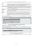
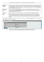
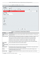
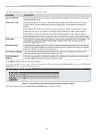
xStack® DGS-3200 Series Layer 2 Gigabit Ethernet Managed Switch CPU Access Profile List Due to a ch ipset limitation and needed extra switch security, the Switch incorporates CPU Interface filtering. This added feature increases t he running sec urity of the Switch by e nabling the use r to c reate a list of access rules for packets des tined for t he Switch's CPU interface. Employed similarly to the Access Profile feature previously mentioned, CPU interface filtering examines Ethernet, IP and Packet Content Mask packet headers destined for the CPU and will either forward them or filter them, based on the user's im plementation. As an ad ded featu re for th e CPU Filtering, th e Switch al lows th e CPU filtering m echanism to be enabled or disabled globally, permitting the user to create various lists of rules without immediately enabling them. Creating an access pro file for the CPU is divided into two basic parts. The first is to specify which part o r parts o f a frame the Switch will examine, such as th e MAC source a ddress or the IP destination address. The second part is en tering the criteria th e Switch will use to determine what to do with the frame. The entire process is described below. Users m ay g lobally en able or d isable th e CPU In terface Filteri ng Stat e mechanism by u sing t he rad io buttons t o ch ange th e running state. Choose Enabled to enable CPU packets to be scrutinized by the Switch and Disabled to disallow this scrutiny. To view the following window, click ACL > CPU Access Profile List: Figure 6 - 23. CPU Access Profile List window This window displays the CPU Access Profile List entries creat ed on the Switch (one CPU access profile of each t ype has been created for explanatory purposes). To view the configurations for an entry, click the corresponding Show Details button. To ad d an en try to th e CPU Access Profile List, click th e Add CPU A CL Pro file button. Th is will op en the Add CPU ACL Profile window, as shown below. To remove all CPU Access Profile List entries, click the Delete All button. The Switch s upports four CPU Access Profile types: Ethe rnet (or MAC address-based) profile c onfiguration, IP (IPv4) addre ssbased profile configuration, IPv6 address-based profile configuration, and Packet Content Mask. 198
-
 1
1 -
2
-
3
-
4
-
5
-
6
-
7
-
8
-
9
-
10
-
11
-
12
-
13
-
14
-
15
-
16
-
17
-
18
-
19
-
20
-
21
-
22
-
23
-
24
-
25
-
26
-
27
-
28
-
29
-
30
-
31
-
32
-
33
-
34
-
35
-
36
-
37
-
38
-
39
-
40
-
41
-
42
-
43
-
44
-
45
-
46
-
47
-
48
-
49
-
50
-
51
-
52
-
53
-
54
-
55
-
56
-
57
-
58
-
59
-
60
-
61
-
62
-
63
-
64
-
65
-
66
-
67
-
68
-
69
-
70
-
71
-
72
-
73
-
74
-
75
-
76
-
77
-
78
-
79
-
80
-
81
-
82
-
83
-
84
-
85
-
86
-
87
-
88
-
89
-
90
-
91
-
92
-
93
-
94
-
95
-
96
-
97
-
98
-
99
-
100
-
101
-
102
-
103
-
104
-
105
-
106
-
107
-
108
-
109
-
110
-
111
-
112
-
113
-
114
-
115
-
116
-
117
-
118
-
119
-
120
-
121
-
122
-
123
-
124
-
125
-
126
-
127
-
128
-
129
-
130
-
131
-
132
-
133
-
134
-
135
-
136
-
137
-
138
-
139
-
140
-
141
-
142
-
143
-
144
-
145
-
146
-
147
-
148
-
149
-
150
-
151
-
152
-
153
-
154
-
155
-
156
-
157
-
158
-
159
-
160
-
161
-
162
-
163
-
164
-
165
-
166
-
167
-
168
-
169
-
170
-
171
-
172
-
173
-
174
-
175
-
176
-
177
-
178
-
179
-
180
-
181
-
182
-
183
-
184
-
185
-
186
-
187
-
188
-
189
-
190
-
191
-
192
-
193
-
194
-
195
-
196
-
197
-
198
-
199
-
200
-
201
-
202
-
203
-
204
-
205
-
 206
206 -
 207
207 -
 208
208 -
 209
209 -
 210
210 -
 211
211 -
 212
212 -
 213
213 -
 214
214 -
 215
215 -
 216
216 -
217
-
218
-
219
-
220
-
221
-
222
-
223
-
224
-
225
-
226
-
227
-
228
-
229
-
230
-
231
-
232
-
233
-
234
-
235
-
236
-
237
-
238
-
239
-
240
-
241
-
242
-
243
-
244
-
245
-
246
-
247
-
248
-
249
-
250
-
251
-
252
-
253
-
254
-
255
-
256
-
257
-
258
-
259
-
260
-
261
-
262
-
263
-
264
-
265
-
266
-
267
-
268
-
269
-
270
-
271
-
272
-
273
-
274
-
275
-
276
-
277
-
278
-
279
-
280
-
281
-
282
-
283
-
284
-
285
-
286
-
287
-
288
-
289
-
290
-
291
-
292
-
293
-
294
-
295
-
296
-
297
-
298
-
299
-
300
-
301
-
302
 |
 |
