D-Link DGS-3200-10 Product Manual - Page 217
Add CPU ACL Profile window for Packet Content, Parameter, Description, Select Profile
 |
UPC - 790069306310
View all D-Link DGS-3200-10 manuals
Add to My Manuals
Save this manual to your list of manuals |
Page 217 highlights
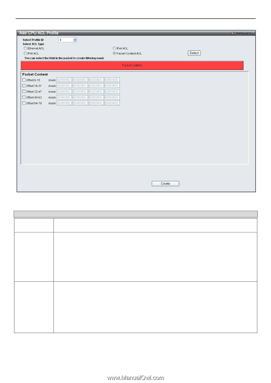
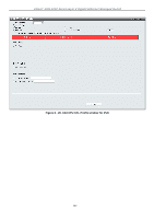
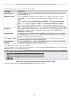
xStack® DGS-3200 Series Layer 2 Gigabit Ethernet Managed Switch Figure 6 - 30. Add CPU ACL Profile window for Packet Content The following parameters may be configured for the Packet Content filter. Parameter Description Select Profile ID Use the drop-down menu to select a unique identifier number for this profile set. This value can be set from 1 to 5. Select ACL Type Select profile based on Ethernet (MAC Address), IPv4 address, IPv6 address, or packet content mask. This will change the menu according to the requirements for the type of profile. Select Ethernet to instruct the Switch to examine the layer 2 part of each packet header. Select IPv4 to instruct the Switch to examine the IPv4 address in each frame's header. Select IPv6 to instruct the Switch to examine the IPv6 address in each frame's header. Select Packet Content Mask to specify a mask to examine the content of the packet header. Offset This field will instruct the Switch to mask the packet header beginning with the offset value specified: 0-15 - Enter a value in hex form to mask the packet from the beginning of the packet to the 15th byte. 16-31 - Enter a value in hex form to mask the packet from byte 16 to byte 31. 32-47 - Enter a value in hex form to mask the packet from byte 32 to byte 47. 48-63 - Enter a value in hex form to mask the packet from byte 48 to byte 63. 64-79 - Enter a value in hex form to mask the packet from byte 64 to byte 79. Click Apply to set this entry in the Switch's memory. 204
-
 1
1 -
2
-
3
-
4
-
5
-
6
-
7
-
8
-
9
-
10
-
11
-
12
-
13
-
14
-
15
-
16
-
17
-
18
-
19
-
20
-
21
-
22
-
23
-
24
-
25
-
26
-
27
-
28
-
29
-
30
-
31
-
32
-
33
-
34
-
35
-
36
-
37
-
38
-
39
-
40
-
41
-
42
-
43
-
44
-
45
-
46
-
47
-
48
-
49
-
50
-
51
-
52
-
53
-
54
-
55
-
56
-
57
-
58
-
59
-
60
-
61
-
62
-
63
-
64
-
65
-
66
-
67
-
68
-
69
-
70
-
71
-
72
-
73
-
74
-
75
-
76
-
77
-
78
-
79
-
80
-
81
-
82
-
83
-
84
-
85
-
86
-
87
-
88
-
89
-
90
-
91
-
92
-
93
-
94
-
95
-
96
-
97
-
98
-
99
-
100
-
101
-
102
-
103
-
104
-
105
-
106
-
107
-
108
-
109
-
110
-
111
-
112
-
113
-
114
-
115
-
116
-
117
-
118
-
119
-
120
-
121
-
122
-
123
-
124
-
125
-
126
-
127
-
128
-
129
-
130
-
131
-
132
-
133
-
134
-
135
-
136
-
137
-
138
-
139
-
140
-
141
-
142
-
143
-
144
-
145
-
146
-
147
-
148
-
149
-
150
-
151
-
152
-
153
-
154
-
155
-
156
-
157
-
158
-
159
-
160
-
161
-
162
-
163
-
164
-
165
-
166
-
167
-
168
-
169
-
170
-
171
-
172
-
173
-
174
-
175
-
176
-
177
-
178
-
179
-
180
-
181
-
182
-
183
-
184
-
185
-
186
-
187
-
188
-
189
-
190
-
191
-
192
-
193
-
194
-
195
-
196
-
197
-
198
-
199
-
200
-
201
-
202
-
203
-
204
-
205
-
206
-
207
-
208
-
209
-
210
-
211
-
 212
212 -
 213
213 -
 214
214 -
 215
215 -
 216
216 -
 217
217 -
 218
218 -
 219
219 -
 220
220 -
 221
221 -
 222
222 -
223
-
224
-
225
-
226
-
227
-
228
-
229
-
230
-
231
-
232
-
233
-
234
-
235
-
236
-
237
-
238
-
239
-
240
-
241
-
242
-
243
-
244
-
245
-
246
-
247
-
248
-
249
-
250
-
251
-
252
-
253
-
254
-
255
-
256
-
257
-
258
-
259
-
260
-
261
-
262
-
263
-
264
-
265
-
266
-
267
-
268
-
269
-
270
-
271
-
272
-
273
-
274
-
275
-
276
-
277
-
278
-
279
-
280
-
281
-
282
-
283
-
284
-
285
-
286
-
287
-
288
-
289
-
290
-
291
-
292
-
293
-
294
-
295
-
296
-
297
-
298
-
299
-
300
-
301
-
302
 |
 |